Following on from the previous posts in this series where we calculated the seismic coefficients from NZS1170.5 and generated ADRS curves. This post covers generating the parts and components coefficient in accordance with Chapter 8 of NZS1170.5. Some time ago I added VBA functions to the GitHub repository to cover this, I just never got round to posting it on the blog.
If you don’t know what a ‘part’ is in terms of seismic loading, get out from under your rock. If you’re attaching something that’s considered to be secondary structure to a structure, and you want to work out how much seismic load to design it for, then you need to be designing this attached structure as a part. It could be a piece of plant, a cladding, a part of the main structure under face loading, basically anything that isn’t the main structure.
Parts loading … What and why?
Often there is a bit of an argument that develops among engineers regarding what exactly might need to be designed for a parts load and what doesn’t. If in doubt all I can say is think very carefully about it and do it anyway, nobody likes stuff falling off buildings and turning people into pancakes.

Photo by Evgheni Russu on Unsplash
If it’s a major part to the building, then ideally you should be modelling it in one form or another as part of your main model which you’re using to design the building to capture its behaviour. Sometimes this is less than ideal, especially when you have a secondary structure or part of the structure with quite a different response to the main system. If this is the case, then design it as a part.
Basically, parts loading is suggesting, your bits you’re attaching are going to see higher accelerations than the seismic accelerations of say a floorplate. This makes sense right, the items have their own response, and it’s no different than how your multistorey building might act sitting on the ground. Whereas higher accelerations are generated within each successive storey than the acceleration of the underlying ground. If you put a smaller building supported on one of your building floors, the upper levels of that smaller building will have a higher acceleration than the floor to which it is attached at its base.
Another aspect you’re left to make you own mind up over is how far do we chase these higher loads back into the structure. In my opinion design the member supporting the part, and its fixings for the load, and make sure there is at least a load path back to the main structure, but beyond designing the part itself, and the fixings to what is supporting it, and sometimes that support member and its fixings it is not expected that you include these higher part loads in the overall analysis of the structure.
To demonstrate, say you have a precast cladding panel, it’s attached to a horizontal steel member at the top that spans between some portal frames. In this situation I’d be designing the cladding panel, the fixings to the panel for parts loads, and I’d be designing the steel member and its fixings back to the portals for the parts loads, but it would not be expected that you’d be designing the portal for the parts loads if they were part of the structures main lateral load resisting system. Basically, use your brain, and don’t get too carried away.
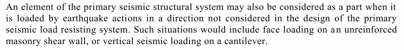
While we’re here (and because I like a good rant), one aspect I always seem to find people doing wrong is for the design of primary structure out-of-plane. For example, say we have a concrete wall, it is part of the main structural system in the in-plane direction, but out-of-plane it is not. What the code says is you need to design any elements required in plane but the main lateral load resisting system for parts loading out-of-plane. This is so they do not form for example a hinge mid-height of the wall which impacts on the wall doing its job in-plane of the wall. No people = pancakes right. The below clause is the offending information that people seem to have some issues with applying and extending to their situation. I’ve even seen some people design said walls out-of-plane for high levels of ductility, whilst relying on the walls in plane, but the force is so high, it wouldn’t work they say if you had to design it for a ductility of 1.0 as a part out-of-plane. Damn right it won’t work in reality at a ductility of 3…. pancakes anyone?
The code…
Anyway, …. resuming normal programming, the parts coefficient VBA code leverages some of the previous code developed for the normal seismic coefficient calculations. So, make sure you grab the full code module from GitHub.

Seismic parts coefficient – Cd,part(T)
Multiply result by the weight of a part to give Fph the seismic parts seismic force. Easy.
Function Loading_C_d_T_part(T_part As Variant, Site_subsoil_class As String, Hazard_factor As Double, Return_period_factor As Double, _
                            R_p As Double, mu_part As Double, h_i As Double, h_n As Double, Optional C_ph_code_values As Boolean = True) As Variant
'Function to calculate the parts and components seismic coefficient

'________________________________________________________________________________________________________________
'USAGE
'________________________________________________________________________________________________________________
'=Loading_C_d_T_intermediate_part(T_part,Site_subsoil_class,Hazard_factor,Return_period_factor,R_p,mu_part,h_i,h_n,C_ph_code_values)
'T_part = PART FIRST MODE PERIOD
'Site_subsoil_class = SITE SUBSOIL CLASS, i.e. A/B/C/D/E (ENTERED AS A STRING)
'Hazard_factor = HAZARD FACTOR Z
'Return_period_factor = RETURN PERIOD FACTOR Ru OR Rs
'mu_part = DUCTILITY OF PART
'h_i = HEIGHT OF ATTACHMENT OF PART
'h_n = HEIGHT FROM THE BASE OF THE STRUCTURE TO THE UPPERMOST SEISMIC WEIGHT OR MASS
'OPTIONAL - C_ph_code_values is optional, when set to TRUE the value is interpolated from the NZS1170.5 TABLE C8.3
'           rounded values. When set to FALSE, the values are calculated based on first principles approach
'________________________________________________________________________________________________________________

    Dim arr_temp As Double
    Dim k As Integer

    'convert to array
    'check if single value provided (i.e. one cell), and convert to 2D array
    If T_part.Rows.count = 1 Then
        T_part = Array(T_part.Value2)
        arr_temp = T_part(0)
        ReDim T_part(1 To 1, 1 To 1)
        T_part(1, 1) = arr_temp
    Else
        'convert to 2D array
        T_part = T_part.Value2
    End If

    Dim C_d_T_part
    ReDim C_d_T_part(LBound(T_part) To UBound(T_part), 1 To 1)

    For k = LBound(T_part) To UBound(T_part)
        C_d_T_part(k, 1) = Loading_C_d_T_intermediate_part(T_part(k, 1), Site_subsoil_class, Hazard_factor, Return_period_factor, _
                                                           R_p, mu_part, h_i, h_n, C_ph_code_values)
    Next k

    'return results
    Loading_C_d_T_part = C_d_T_part

End Function

Private Function Loading_C_d_T_intermediate_part(T_part As Variant, Site_subsoil_class As String, Hazard_factor As Double, Return_period_factor As Double, _
                                                 R_p As Double, mu_part As Double, h_i As Double, h_n As Double, Optional C_ph_code_values As Boolean = True)
'Function to calculate C_d(T) for parts and components loading, the parts seismic load coefficient for a single period T

'________________________________________________________________________________________________________________
'USAGE
'________________________________________________________________________________________________________________
'=Loading_C_d_T_intermediate_part(T_part,Site_subsoil_class,Hazard_factor,Return_period_factor,R_p,mu_part,h_i,h_n,C_ph_code_values)
'T_part = PART FIRST MODE PERIOD
'Site_subsoil_class = SITE SUBSOIL CLASS, i.e. A/B/C/D/E (ENTERED AS A STRING)
'Hazard_factor = HAZARD FACTOR Z
'Return_period_factor = RETURN PERIOD FACTOR Ru OR Rs
'mu_part = DUCTILITY OF PART
'h_i = HEIGHT OF ATTACHMENT OF PART
'h_n = HEIGHT FROM THE BASE OF THE STRUCTURE TO THE UPPERMOST SEISMIC WEIGHT OR MASS
'OPTIONAL - C_ph_code_values is optional, when set to TRUE the value is interpolated from the NZS1170.5 TABLE C8.3
'           rounded values. When set to FALSE, the values are calculated based on first principles approach
'________________________________________________________________________________________________________________

    Dim C_T0_part
    Dim C_Hi_part
    Dim C_i_T_part
    Dim C_ph_part
    Dim C_d_T_part
    Dim Z_R_product

    'check if Z x R > 0.7, if so limit product to 0.7 for calculating C_T
    If Hazard_factor * Return_period_factor > 0.7 Then
        Z_R_product = 0.7
    Else
        Z_R_product = Hazard_factor * Return_period_factor
    End If

    'Elastic site spectra for T=0 seconds for modal response spectrum method
    C_T0_part = Loading_C_T(0, Site_subsoil_class, Hazard_factor, Return_period_factor, "N/A", False)

    'Determine floor height coefficient
    C_Hi_part = Loading_C_Hi(h_i, h_n)

    'determine part or component spectral shape coefficient
    C_i_T_part = Loading_C_i_T_p(T_part)

    'determine part horizontal response factor from first principles calculation, this will result in slightly different values as
    'the results are not rounded like the code values (refer commentary for tabulated values)
    C_ph_part = Loading_C_ph_part(mu_part, C_ph_code_values)

    'Horizontal design action coefficient
    C_d_T_part = C_T0_part * C_Hi_part * C_i_T_part * C_ph_part * R_p

    'Check for maximum level design coefficient of 3.6
    If C_d_T_part > 3.6 Then C_d_T_part = 3.6

    'return results
    Loading_C_d_T_intermediate_part = C_d_T_part

End Function
Part Response Factor – Cph
Function Loading_C_ph_part(mu_part As Double, Optional C_ph_code_values As Boolean = True)
'Function to return the part response factor, calculated from first priciples based on the TABLE C8.3 in the commentary of NZS1170.5
'or from TABLE C8.3 values

'refer following Loading_k_mu_part and Loading_Sp_1170 for basis of the first principles calculation

'________________________________________________________________________________________________________________
'USAGE
'________________________________________________________________________________________________________________
'=Loading_C_ph_part(mu_part,C_ph_code_values)
'mu_part = DUCTILITY OF PART
'OPTIONAL - C_ph_code_values is optional, when set to TRUE the value is interpolated from the NZS1170.5 TABLE C8.3
'           rounded values. When set to FALSE, the values are calculated based on first principles approach
'________________________________________________________________________________________________________________

    Dim mu_part_array
    Dim C_p_round_array
    Dim lower_bound_index As Long
    Dim upper_bound_index As Long
    Dim i As Long

    If C_ph_code_values Then
        'determine part horizontal response factor from code rounded values in TABLE C8.3
        mu_part_array = Array(1, 1.25, 1.5, 1.75, 2, 3, 6)
        C_p_round_array = Array(1, 0.85, 0.75, 0.65, 0.55, 0.45, 0.45)
        'interpolate for C_ph value
        'determine upper bound index
        For i = LBound(mu_part_array) To UBound(mu_part_array)
            'determine in what band the actual ductility lies
            If mu_part <= mu_part_array(i) Then
                upper_bound_index = i
                GoTo skip_code1
            End If
        Next i
skip_code1:
        'determine lower bound index
        For i = UBound(mu_part_array) To LBound(mu_part_array) Step -1
            'determine in what band the actual ductility lies
            If mu_part >= mu_part_array(i) Then
                lower_bound_index = i
                GoTo skip_code2
            End If
        Next i
skip_code2:

        'interpolate for code C_ph value based on mu_part
        If lower_bound_index = upper_bound_index Then
            Loading_C_ph_part = C_p_round_array(lower_bound_index)
        Else
            Loading_C_ph_part = C_p_round_array(lower_bound_index) * _
                                (1 - (mu_part - mu_part_array(lower_bound_index)) / (mu_part_array(upper_bound_index) - mu_part_array(lower_bound_index))) + _
                                C_p_round_array(upper_bound_index) * _
                                ((mu_part - mu_part_array(lower_bound_index)) / (mu_part_array(upper_bound_index) - mu_part_array(lower_bound_index)))
        End If

    Else
        'determin part horizontal response factor from first principles
        Loading_C_ph_part = Loading_S_p_1170(mu_part) / Loading_k_mu_part(mu_part)
    End If

End Function
Floor Height Coefficient – CHi
Working out this one by hand always confuses the hell out of me, the way the height limits are explained in the code I find very confusing. Luckily, I have this and I don’t need to care about it anymore!
Function Loading_C_Hi(h_i As Double, h_n As Double)
'Function to calculate C_Hi the floor height coefficient for parts & components loading

'________________________________________________________________________________________________________________
'USAGE
'________________________________________________________________________________________________________________
'=Loading_C_Hi(h_i,h_n)
'h_i = HEIGHT OF ATTACHMENT OF PART
'h_n = HEIGHT FROM THE BASE OF THE STRUCTURE TO THE UPPERMOST SEISMIC WEIGHT OR MASS
'________________________________________________________________________________________________________________

    Dim C_Hi1 As Double
    Dim C_Hi2 As Double
    Dim C_Hi3 As Double

    C_Hi1 = 1 + h_i / 6
    C_Hi2 = 1 + 10 * (h_i / h_n)
    C_Hi3 = 3

    If h_i < 12 Or h_i < 0.2 * h_n Then
        Loading_C_Hi = WorksheetFunction.Min(C_Hi1, C_Hi2)
    ElseIf h_i < 0.2 * h_n Then
        Loading_C_Hi = C_Hi2
    Else
        Loading_C_Hi = C_Hi3
    End If

End Function
Part Spectral Shape Coefficient – Ci(Tp)
Function Loading_C_i_T_p(T_part As Variant)
'Function to calculate Ci(Tp) the part spectral shape coefficient for parts & components loading

'________________________________________________________________________________________________________________
'USAGE
'________________________________________________________________________________________________________________
'=Loading_C_i_T_p(T_part)
'T_part = PART FIRST MODE PERIOD
'________________________________________________________________________________________________________________

    If T_part <= 0.75 Then
        Loading_C_i_T_p = 2
    ElseIf T_part >= 1.5 Then
        Loading_C_i_T_p = 0.5
    Else
        Loading_C_i_T_p = 2 * (1.75 - T_part)
    End If

End Function
Part Inelastic Spectrum Scaling Factor – kμ,part
Function Loading_k_mu_part(mu_part As Double)
'Function to return the k_mu factor appropriate for parts, determined from values in TABLE C8.3 in NZS1170.5 commentary.

'________________________________________________________________________________________________________________
'USAGE
'________________________________________________________________________________________________________________
'=Loading_k_mu_part(mu_part)
'mu_part = DUCTILITY OF PART

'NOTE - the calculated values in TABLE C8.3 are consistent, with the calculation at T = 0 seconds,
'       using any soil classification except "E" and the following relationship
'       k_mu_part = (k_mu - 1) / 2 + 1
'       This will result in the values in TABLE C8.3 being actually calculated without any rounding
'________________________________________________________________________________________________________________

    Dim Site_subsoil_class As String

    Site_subsoil_class = "A"    'could use any value here apart from "E"

    Loading_k_mu_part = (Loading_k_mu(0, Site_subsoil_class, mu_part) - 1) / 2 + 1

End Function
NZS1170.5 Structural Performance Factor – SP
Function Loading_S_p_1170(mu As Double)
'Function to return an Sp factor in accordance with NZS1170.5 CL4.4.2

'________________________________________________________________________________________________________________
'USAGE
'________________________________________________________________________________________________________________
'=Loading_S_p_1170(mu_part)
'mu = DUCTILITY
'________________________________________________________________________________________________________________

    Loading_S_p_1170 = 1.3 - 0.3 * mu

    'check lower limit if S_p < 0.7
    If Loading_S_p_1170 < 0.7 Then Loading_S_p_1170 = 0.7

End Function
Thats all the code you need.
Some random observations: –
One interesting thing I noted in generating this code is that Table C8.3 in the code commentary for Cph (shown below) suggests they are just working out the resulting factor based on the normal provisions, this isn’t the case though. They seem to use a special derivation for Inelastic spectrum scaling factor (kμ).and then, only based on kμ for subsoil classes A to D with T1 = 0.0 seconds.
How do I know this, well I get quite different values than the table unless I use the relationship noted below, I just plugged and chugged some numbers until I recognised the pattern they were utilising?

I’ve given the option to calculate specifically, or to just interpolate from the rounded table values, refer to the function input variables for Loading_k_mu_part() .
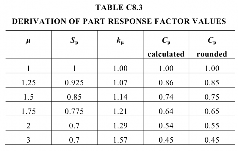
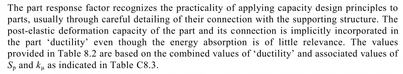
Why are the code writers using this derivation vs the normal kμ derivation which is based on subsoil type, period and ductility, who knows, but it probably has to do with the following excerpt from the commentary which sort of implies a whole lot of other things are implicitly accounted for in the parts ductility and the resultant parts force, not just “ductility” like we might think of it for working out a non-parts load. Maybe I’m reading too much into it thought to try and explain the other way it is worked out.
Thats all I have on the matter, if you have any questions on usage of the user defined functions either post a comment here or raise an issue on the GItHub repository.
Hi,
I’m designing a suspended slab supported by SHS steel columns. I would like to hear your thoughts on AS4100 stating that we should design steel columns for a minimum eccentricity of 100mm?
A 89×6 SHS can take 324kN in compression, however if I consider 100mm eccentricity, this number drops to 115kN. Do you think there’s a case where I can consider pure compression and disregard this eccentricity?
Thanks,
Hi Gabriel
Unfortunately you either use those provisions and detail it to be within reason as pin like as possible, or you deal with the continuity you’ve created if you’ve got some fixity. The provisions are intended to impart some minimal level of robustness to the columns which are a critical component in any system. If that means upping the column sizes to increase the moment capacity and axial capacity then so be it.