So if you’ve been following along with this series you now hopefully know a little bit more about some of the methods involved in undertaking buckling analyses. Pat yourself on the back for making it this far through my ramblings I guess (if nothing else).
It’s pretty simple, and in most cases it will yield a capacity very similar to the code hand methods, albeit via a completely different path. It’s always good when different methods yield similar results.
The EngTips post I mentioned in the part 1 post in this series did highlight to me one possible area where the results from the code ‘hand methods’ and a flexural buckling analyses seemed to possibly significantly part ways.
This aforementioned post degenerated into checking many cases with continuous lateral ‘L’ restraints to a single flange and the beams subject to reverse bending (a change between positive and negative bending actions) along the span.
If you could follow along then apparently these checks based on others work seemed to highlight a significant difference in buckling moments, and hence the design capacities that might be achieved. I won’t lie, this surprised me (and perplexed me), could the code writers have possibly got it wrong? Anythings possible I guess.
The rest of this post will investigate the curious case of the 70′ beam that people were first looking at to try highlight the differences that people were describing. Can I see the same thing? Lets find out…
The curious case of the 70′ beam
Now that has a better ring to it than the curious case of the 21336mm beam. Despite that we will do this exercise in metric, not that imperial rubbish. Unfortunately that imperial stuff is still practiced in a few backwater countries around the world ;). One day they will see the light.. Base 10 people, it’s first world stuff!
Given the following scenario what we hope to show is either that we get the same (or similar) answers for the capacity in the critical end segment, or we won’t. Very much a binary conclusion (I hope), which will in turn confirm some sort of point that I’m trying to make.
We’ll keep it fairly basic to demonstrate the point. This time round we’ll use LTBeamN to do the buckling analysis for shits and giggles. Primarily because it allows us to put discrete restraints of any type anywhere on the cross section. Because LTBeamN is doing some sort of 3D finite element thing it has the options to do this, versus needing to basically fudge it in Mastan2 with its ‘frame’ elements and no surety that your bodge to add a restraint to the top flange is really the right way to go about these things. Nothing to say LTBeamN is doing it ‘right’ either…. whatever ‘right’ might be defined as in this case.
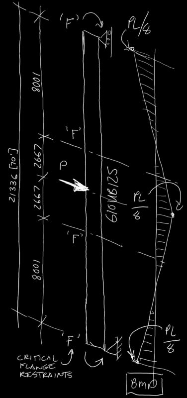
So assuming only ‘F’ type restraints at a couple of central locations to fully define the design segments in our member as a control, and ‘L’ type restraints for our actual design case we march on. If theres something fundamentally wrong with the buckling analysis method we should see similar divergences from the hand method results for both ‘F’ & ‘L’ restraints.
End restraints are ‘F’ type full restraints at the supports, a requirement at supports in NZS3404/AS4100. The load is applied in a way that it’s application is constrained so it acts through the shear center.
Hopefully we will show the same effect noted in the EngTips post regarding ‘L’ type restraints. This being that the buckling analyses can give a much higher or lower design capacity than the traditional code effective length ‘hand method’.
Note I have purposely not linked to this EngTips post I’ve mentioned throughout this series, as it contains a lot of misadventures, with participants doing all sorts of analyses, sometimes right and/or wrong in the pursuit of the truth.
But feel free to search it out and read 600 odd posts and come to your own conclusions about all things buckling related and AS4100/NZS3404 related. If you’re up for that kind of ‘fun’ search EngTips for Rafter without fly brace?
Section properties
For the 610UB125 specified, the relevant section properties well need are:-


 &
&  as per earlier posts in this series.
Results… ‘F’ Restraints
Hand check first.. ‘F’ Restraints
Lets start with the hand method check and ‘F’ restraints, assuming the 1st segment with  is critical:-

Since  ,
,  &
&  for this scenario we are looking at an effective length of:-

It’s worth noting here that with the ‘F’ restraints that the next segment that is much shorter would definitely have full lateral restraint (FLR), so  could be taken as
  for this adjacent segment in accordance with CL 5.4.3.4.1. So lets take advantage of this, as the buckling analysis certainly is accounting for this improvement in the buckling due to the member continuity.
Therefore revised 
Therefore calculating the reference buckling moment:-
![M_{oa}=M_o= \displaystyle{ \sqrt{\bigg\{\bigg(\frac{\pi^2\times205000\times 39.3\times10^6 }{6801^2}\bigg)\bigg[78846.15\times1560\times10^3 +\bigg(\frac{\pi^2\times205000\times 3450\times10^9 }{6801^2}\bigg) \bigg] \bigg\} }}](https://engineervsheep.com/wp-content/ql-cache/quicklatex.com-a2561ab1b0f5ba89fb67364df8276ca7_l3.png "Rendered by QuickLaTeX.com")

![\alpha_s=\displaystyle{0.6\bigg\{\sqrt{\bigg[\bigg(\frac{684.2}{1030.4}\bigg)^2+3\bigg]}-\bigg(\frac{684.2}{1030.4}\bigg)\bigg\}}](https://engineervsheep.com/wp-content/ql-cache/quicklatex.com-cf8c2ce0baa9d236aa69c774e96dacd4_l3.png "Rendered by QuickLaTeX.com")

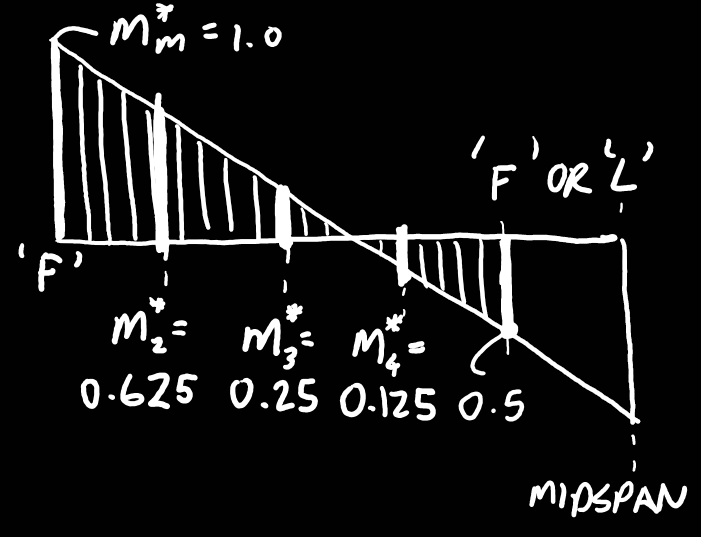
Considering the following moment diagram in terms of ratios of the maximum moment at midspan and the support, we can calculate the  factor using eqn 5.6.1.1(2):-


In this scenario we achieve full lateral restraint, i.e. 
Buckling check second.. ‘F’ Restraints


Therefore from our analysis we can see that the elastic buckling bending moment  . Since is the same as above, this means from CL 5.6.4 the reference buckling moment is:-


![\alpha_s=\displaystyle{0.6\bigg\{\sqrt{\bigg[\bigg(\frac{636.4}{1030.4}\bigg)^2+3\bigg]}-\bigg(\frac{636.4}{1030.4}\bigg)\bigg\}}](https://engineervsheep.com/wp-content/ql-cache/quicklatex.com-a9a1ec1c91a2cb2e2692f7e6003d94b8_l3.png "Rendered by QuickLaTeX.com")

Note this is slightly less than calculated using the hand method. It’s also worth noting that had we not used  , that we would be significantly better here by using the buckling analysis route. As it captures the effect of the beam continuity due to the short segment adjacent to the segment we are looking at.

Again in this scenario we achieve full lateral restraint, i.e. .
Ignoring the fact that we ended up having FLR in both cases, comparison with the hand and buckling analysis methods results shows that the hand method estimated the capacity at  . Versus the buckling analysis route estimating the capacity at
  . A difference of approximately five percent. Not too bad I guess…
Results… ‘L’ Restraints
So lets do the same process we did above, but this time assuming all three internal restraints are ‘L’ type lateral restraints to the top critical compression flange. The assumption is that the ‘L’ restraints prevent lateral restraint/displacement of the critical flange, but they do not provide any twist restraint.
Hand check first.. ‘L’ Restraints
Given we now have a ‘FL’ segment, we cannot take advantage of the adjacent segment having FLR in this case. Therefore , & for this scenario. So we are looking at an effective length of:-
Therefore calculating the reference buckling moment:-
![M_{oa}=M_o= \displaystyle{ \sqrt{\bigg\{\bigg(\frac{\pi^2\times205000\times 39.3\times10^6 }{8001^2}\bigg)\bigg[78846.15\times1560\times10^3l +\bigg(\frac{\pi^2\times205000\times 3450\times10^9 }{8001^2}\bigg) \bigg] \bigg\} }}](https://engineervsheep.com/wp-content/ql-cache/quicklatex.com-4ca99b6a21b3e3839bc9063708c81450_l3.png "Rendered by QuickLaTeX.com")

![\alpha_s=\displaystyle{0.6\bigg\{\sqrt{\bigg[\bigg(\frac{535.0}{1030.4}\bigg)^2+3\bigg]}-\bigg(\frac{535.0}{1030.4}\bigg)\bigg\}}](https://engineervsheep.com/wp-content/ql-cache/quicklatex.com-835b138fee38ef3d2acd56f3a9e453ca_l3.png "Rendered by QuickLaTeX.com")

again.

 , slightly less than achieving FLR.
Buckling check second.. ‘L’ Restraints


Now you should be able to immediately see the difference in buckling mode and magnitude of the buckling moment, with the ability of the beam to rotate about the top flange with the right hand ‘L’ lateral restraint compared to the earlier result with ‘F’ full restraint.
Therefore similar to previous the elastic buckling bending moment is  . Again is the same as above, so:-


![\alpha_s=\displaystyle{0.6\bigg\{\sqrt{\bigg[\bigg(\frac{295.7}{1030.4}\bigg)^2+3\bigg]}-\bigg(\frac{295.7}{1030.4}\bigg)\bigg\}}](https://engineervsheep.com/wp-content/ql-cache/quicklatex.com-f152e6e5d1a9bf201081884d27f19557_l3.png "Rendered by QuickLaTeX.com")


Well, there you have it, completely different answers for this scenario…. it begs the question of what method is right as both approaches are allowed by the code?
Compare the above result to the hand method answer of  and hello Houston we have a problem. In that our answers seem slightly outside the margin of acceptable differences (one is ~63% higher). This is the surprising thing given they are supposed to be valid methods for calculating exactly the same thing.
Now on the face of it you’d say the hand method was significantly over estimating the design capacity. However, quite the opposite could also be true, in that the buckling analysis method in the case of ‘L’ restraints significantly under estimates the design capacity.
Conclusions…
Why the large difference, I really have no idea. Before this came to my attention I’d use the code hand method without a second thought. Now I’m not so sure it’s correct if you’re using ‘L’ restraints in regions where you have a moment reversal.
Is it a significant error on the part of the code? Quite possibly. The curve fitting exercise undertaken for  , was (as I understand it) based on a whole lot of experimental results from simply supported beams with various loads applied. So no reversal of moment in sight for the curve fitting exercise.
But maybe the code writers took all this into account? I certainly don’t know for sure, but on the face of following the buckling analysis route it certainly seems like there opportunity for a significant divergence in the design capacity that’s derived between the two methods.
It’s hard to see how the code writers wouldn’t have accounted for this, but who knows.
So maybe the moral of this story is to avoid reliance on ‘L’ restraints in regions where the moment is reversing. Only rely on ‘F’ or ‘P’ type restraints, as our results showed reasonable agreement between the two methods in the first cases that were checked. I’ll certainly think twice about pledging undying allegiance to the ‘L’ restraint in future….
Maybe this buckling analysis rabbit hole we went down isn’t the great defining method we had hoped, or maybe it actually is and it’s exposed some flaws in our code approach… you be the judge using some engineering judgement… avoid being the Sheep, be the Engineer!
Onward to fame and fortune or collapse depending on your point of view… I don’t think I’ll ever look at an ‘L’ restraint the same way ever again…
Part 6 here.
Not that it would have altered your answer, but I believe a number of the moments input into the equation should have been negative i.e. (-Mx)^2.
Like I said, wouldn’t impact the answer.
Hi Mat, yeah strictly speaking I guess it should really be noted as the square of a negative number. Force of habit I guess for me in just dropping the negative as it’s effectively redundant!