In the last post we looked at the basic method of undertaking a flexural buckling analysis using Mastan2 and interpretation of the results. We compared a couple of the built-in equations in AS4100 & NZS3404 relating to the moment modification factor and got reasonable agreement.
I stressed that getting the elastic buckling moment out of a buckling analysis does not equate to determining the design capacity. We briefly mentioned the  factor in passing. This is a scaling factor which is determined from the reference buckling moment
  and the nominal section capacity of the member in bending
  , it is intended to essentially account for a number of 2nd order effects. Basically, converting our theoretical buckling value to a “design” value that accounts for real-world things like the fact that all members have initial imperfections (they are not perfectly straight), all beams have some degree of residual stresses (which results in some regions of the section yielding prior to others and resulting in reductions in stiffness with respect to the resistance to buckling).
Basically it’s this relationship from CL 5.6.1:-
![\alpha_s=\displaystyle{0.6\bigg\{\sqrt{\bigg[\bigg(\frac{M_{sx}}{M_{oa}}\bigg)^2+3\bigg]}-\bigg(\frac{M_{sx}}{M_{oa}}\bigg)\bigg\}}](https://engineervsheep.com/wp-content/ql-cache/quicklatex.com-1f892de52441b5df327d49c38718220b_l3.png "Rendered by QuickLaTeX.com")
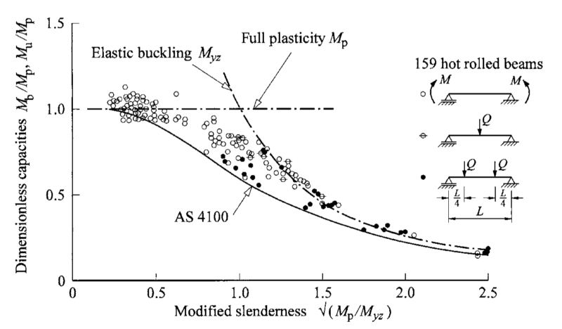
The way the factor works in theory is that it is a curve fit semi-empirical relationship to experimental data, so it’s intended to be a lower bound approach. In theory all real member behaviour is intended to have a higher buckling capacity than the design provisions might calculate. Which is pretty standard stuff as far as design goes the world over!
Now let’s look at extending what we’ve learnt so far with an example of something you might come across in a real world example.
Flexural buckling example…
We’ve talked about idealised restraints, and the pretty pictures in the code showing the subtle distinction between the different types of restraints considered by AS4100 & NZS3404. However, what do you do if you’re not sure if you have a F, a P or an L restraint.
The differences between the Full and Partial restraints is fairly subtle, going on about effective twist or lateral restraint vs partial twist or lateral restraint.
But in terms of design, they go on to basically be almost the same, for example a segment with FF, FP or PP end restraints is for all intents and purposes going to end up with the same or similar effective length if you follow the normal design provisions as the load height factor  and rotation restraint factor
  are identical for these conditions. Only the twist restraint factor
  is different, and the difference is relatively small.
For say a 410UB54 of 8 meters length, this would be  (FF segment),
  (FP segment) or
  (PP segment). So overall not a large difference, but obviously some impact on capacity. But just not as pronounced as when the other and factors come into the equation.
Many of the pretty pictures imply being connected to stiff or flexible members to achieve a given degree of restraint. But what if that restraint isn’t so clear cut to define, at what point is something deemed “flexible“or “stiff” or “effective” for example: –
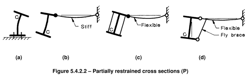
One person’s effective as another’s ineffective, its all very subjective, you say potatoe, I say potato… …. This is where a flexural torsional buckling analysis can help, as you can model specific restraint stiffness conditions to directly reflect the degree of restraint, and hence it’s effectiveness in driving a higher mode of buckling.
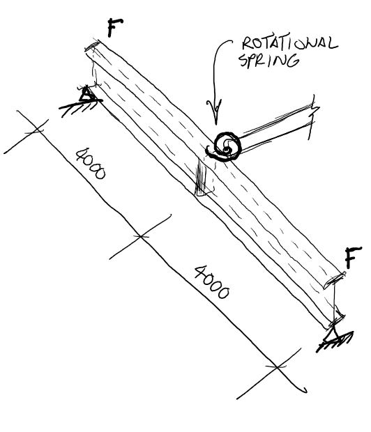
Lets say we have the following example, a stock standard simply supported 410UB54 primary beam (8m long), with a secondary member framing into the web more or less at mid web height level (to keep it simple) providing rotational restraint to the primary beam at the mid span location. There are sufficient stiffeners to ensure the flanges are engaged and the end supports are sufficient to be classified as F restraints: –
Basically, we are attempting to replicate something like either (b) or (c) from the figure 5.4.2.2 above, but without the lateral restraint. Essentially to see at what point higher mode failure modes/behaviour might kick in. This rotational only restraint isn’t really covered by the nice little pictures in AS4100/NZS3404, but notwithstanding this it’s still a valid restraint for increasing a member’s resistance to lateral torsional buckling.
What stiffness member do we need to provide before we get a higher mode of buckling? I’d note at this point that AS4100 is devoid of any recommendations in respect of this, but the NZS3404 commentary has some specifics around relative depths and connection types to achieve “moment” fixings and defining “stiff” vs “flexible” members for those interested.
Anyway… we’re halfway through this post and all we’ve done is waffle on about theories this and theories that…so it’s time to put rubber to the road and prove something (and more pictures).
Buckling stuff.. finally
So basically, what we are trying to demonstrate here is that the development of buckling resistance is dependent on the stiffness of the restraining system. We’ve done this by assuming a rotational spring at the end of the secondary member to represent a rotational restraint. We then alter its rotational stiffness, until we reach a point where there is no further increase in the buckling moment.
Our primary member has an equal and opposite moment applied to both ends, such that we have a constant moment along the member i.e.  case.
case.
By altering the rotational spring stiffness at the end of the secondary member we can determine the critical buckling moment of the primary member at a number of data points through the use of an ‘Elastic Critical Load’ analysis in Mastan2, results below: –
| ROTATIONAL SPRING STIFFNESS | CRITICAL BUCKLING MOMENT |
| 1000 | 295.16 |
| 750 | 295.16 |
| 500 | 295.16 |
| 425 | 295.16 |
| 400 | 295.16 |
| 390 | 295.16 |
| 387.5 | 295.16 |
| 385 | 294.86 |
| 375 | 293.62 |
| 350 | 290.30 |
| 300 | 282.48 |
| 275 | 277.85 |
| 225 | 266.63 |
| 200 | 259.75 |
| 175 | 251.75 |
| 150 | 242.33 |
| 125 | 231.06 |
| 100 | 217.34 |
| 75 | 200.18 |
| 50 | 177.94 |
| 25 | 147.3 |
| 0 | 98.83 |
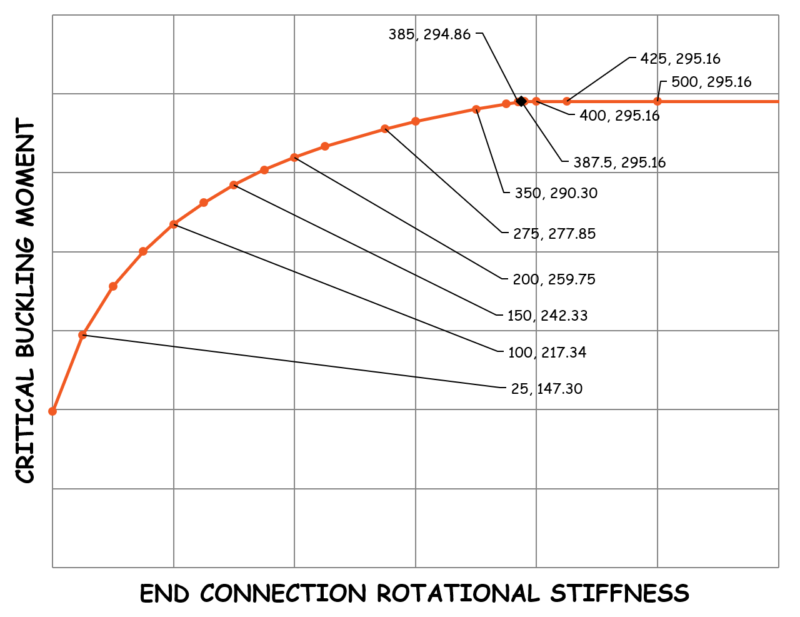
Hopefully, the observant among you will note that there is a relationship between the stiffness and the buckling moment, and that you don’t need a whole lot of stiffness to get pretty close to the maximum buckling behaviour due to the non-linear nature of this relationship.
For example, if we have 50% of the critical rotational stiffness, we get a buckling moment of 88% of the maximum from the data above. This will of course be different for every scenario, but you get the idea.
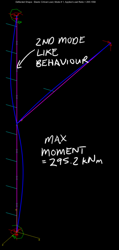
There is also a clear division between the 1st mode failure behaviour and the higher 2nd mode behaviour in the results of the buckling analysis, as shown below
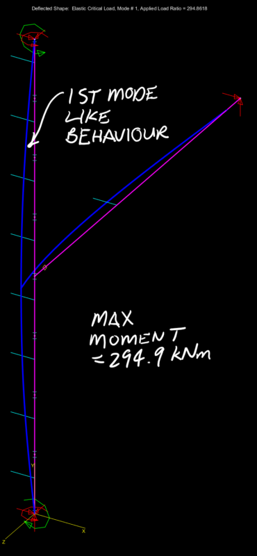
Push the rotational spring stiffness just a little further and we get the higher mode of buckling rearing its head as shown below. Push the stiffness further and as expected there is nothing to gain as can be seen in the graph and results above with the horizontal line past the point of the critical buckling moment when the higher mode fully kicks in.
So, using the results of the buckling analysis to determine the capacity…
From our buckling analysis  &
&  due to the constant moment gradient.
Therefore 
![\alpha_s=\displaystyle{0.6\bigg\{\sqrt{\bigg[\bigg(\frac{339.2}{295.2}\bigg)^2+3\bigg]}-\bigg(\frac{339.2}{295.2}\bigg)\bigg\}}](https://engineervsheep.com/wp-content/ql-cache/quicklatex.com-1bcc0c64f7ada3cae8dc990ac9a3bc80_l3.png "Rendered by QuickLaTeX.com")

Therefore 

So, what if we calculated the capacity by hand from the code for comparison…
For FF segment of half the member length  :-
:-

Since  ,
,  &
&  for the given scenario we are looking at: –

Therefore, calculating the reference buckling moment (see previous post for section properties and material properties being used to match the Mastan analysis):-
![M_{oa}=M_o= \displaystyle{ \sqrt{\bigg\{\bigg(\frac{\pi^2\times205000\times 10.3\times10^6 }{4000^2}\bigg)\bigg[78846.15\times234\times10^3 +\bigg(\frac{\pi^2\times205000\times 394\times10^9 }{4000^2}\bigg) \bigg] \bigg\} }}](https://engineervsheep.com/wp-content/ql-cache/quicklatex.com-c3349719514316e218fed06683d3e71e_l3.png "Rendered by QuickLaTeX.com")

![\alpha_s=\displaystyle{0.6\bigg\{\sqrt{\bigg[\bigg(\frac{339.2}{298.2}\bigg)^2+3\bigg]}-\bigg(\frac{339.2}{298.2}\bigg)\bigg\}}](https://engineervsheep.com/wp-content/ql-cache/quicklatex.com-697bb5d2fcc07ef635776862bcbdfe47_l3.png "Rendered by QuickLaTeX.com")


Appreciate here in this situation that we got almost the same answer  via buckling analysis vs
  via code hand method. (It’s always good when things like this actually work…)
Conclusion
Of importance to recognise is we didn’t have to determine or evaluate any effective lengths if we went down the buckling analysis rabbit hole. Because this aspect is inherently baked into the buckling analysis. Provided of course that we can model the restraint stiffness directly (be it lateral or rotational) we are good to go.
Now ask yourself, what would you do if you had a rotational spring of some random stiffness, or the member restraining the beam that was quite flexible. Well in those situations you cannot use the code requirements to determine the effective length, because you could be lying in the region below where the true higher mode response kicks in. Incorrectly applying the code provisions in these situations could lead to you under or overestimating the true capacity.
This is why a buckling analysis in the right hands (those with sheep tendencies are definitely excluded here) is such a powerful tool for evaluating fringe cases, where the code hand methods of evaluating effective lengths fall flat on their ass.
Use your newfound knowledge wisely…
Part 5 here.
Awesome post! Keep up the great work! 🙂
Very interesting and usefull blog series thanks