This blog post is inspired by a recent post which I responded to on the EngTips forum. The question was related to finding the warping constant of back to back cold formed channels.
The poster was querying the validity of some random formula for calculating the warping constant for back to back channels that they found in another post. Comparing this to values that were published for the shape they were interested in, and they were ultimately getting limited agreement.
This post helps to highlight a few things:-
- You can’t always believe in random formulas you find on the internet
- Random formulas found on the internet may not be applicable to your situation
- Most formulas for complicated section properties like the warping or torsion constants are at best simplified “estimates”
- Some published section properties use these “estimates” and are therefore not that accurate
- Some section properties of built-up shapes are dependent on how the individual members are connected together
The following examples help to highlight the inherent error in using these “estimates” by analysing the section using FEM. Often the simplified formulas do not explicitly account for the curved corner radii present in cold formed sections. As such they can over/under estimate the value of a section property and you’ll be none the wiser.
In this particular case the poster wanted to validate the warping constant for the following shape:-

Using the bloody excellent section-properties python package, I set out to help this poor soul.
To work out the torsion constant (typically termed  ) or warping constant (typically termed
  or
or  ) accurately you really need to use a first principles approach and evaluate the fundamental governing equations that are involved.
Luckily for us section-properties does all the heavy lifting and undertakes an FEM analysis based on the above approach. The package can analyse any section or composite section you could ever think up. In my opinion it’s easily as good as many commercial products (such as IES Shapebuilder) that are designed to do the same thing, and it’s free, and free is good. At the time of writing this post Shapebuilder for example is 795(USD) to purchase a single user perpetual license + annual maintenance. That’s a lot of extra dollars in your pocket for the small price of needing to know a tiny bit of Python.
The package also includes many predefined structural section types to make it easy to quickly get an answer with just a few lines of code for common shapes.
I’d point out at this point I jumped in and created the following double channel section in the hope it would confirm at least that the published values were the same and job done. Of course they weren’t the same as you can see (welcome to structural engineering where nothing works first time!). Engineering can be frustrating at times.
import sectionproperties.pre.sections as sections
from sectionproperties.analysis.cross_section import CrossSection

# geometry of example channel
t = 1.16
d = 150
b = 40
l = 15
r_out = 3 + t
n_r = 12

# published properties
pub_area = 592  # area
pub_i_y = 57.2  # major radius of gyration
pub_i_z = 18  # minor radius of gyration
pub_I_y = 1.936 * 10 ** 6  # major second moment of inertia
pub_I_z = 19.13 * 10 ** 4  # minor second moment of inertia
pub_I_w = 4.931 * 10 ** 8  # warping constant
pub_J = 266  # torsion constant

# create 2 channels, mirror second channel
channel1 = sections.CeeSection(d=d, b=b, l=l, t=t, r_out=(r_out), n_r=n_r)
channel2 = sections.CeeSection(d=d, b=b, l=l, t=t, r_out=(r_out), n_r=n_r)
channel2.mirror_section(axis='y', mirror_point=[0, 0])

# merge the two channels into a single section
geometry = sections.MergedSection([channel1, channel2])

# clean the geometry
geometry.clean_geometry()

# create the analysis mesh
mesh = geometry.create_mesh(mesh_sizes=[0.25, 0.25])

# define the analysis CrossSection
section = CrossSection(geometry, mesh)

# plot the mesh
section.plot_mesh()

# undertake the analysis
section.calculate_geometric_properties()
section.calculate_warping_properties()

# query selected results of interest
area = section.get_area()
i_y, i_z = section.get_rc()
I_y, I_z, _ = section.get_ig()
I_w = section.get_gamma()
J = section.get_j()

# print results
print(f'A = {area:.2f} vs ({pub_area:.2f}) Error = {100*(1-pub_area/area):.3f}%')
print(f'i_y = {i_y:.2f} vs ({pub_i_y:.2f}) Error = {100*(1-pub_i_y/i_y):.3f}%')
print(f'i_z = {i_z:.2f} vs ({pub_i_z:.2f}) Error = {100*(1-pub_i_z/i_z):.3f}%')
print(f'I_y = {I_y:.2f} vs ({pub_I_y:.2f}) Error = {100*(1-pub_I_y/I_y):.3f}%')
print(f'I_z = {I_z:.2f} vs ({pub_I_z:.2f}) Error = {100*(1-pub_I_z/I_z):.3f}%')
print(f'I_w = {I_w:.2f} vs ({pub_I_w:.2f}) Error = {100*(1-pub_I_w/I_w):.3f}%')
print(f'J = {J:.2f} vs ({pub_J:.2f}) Error = {100*(1-pub_J/J):.3f}%')
# Calculated value vs (Published value)
A = 578.00 vs (592.00) Error = -2.422%
i_y = 56.70 vs (57.20) Error = -0.888%
i_z = 18.01 vs (18.00) Error = 0.029%
I_y = 5109205.80 vs (1936000.00) Error = 62.108%
I_z = 187379.37 vs (191300.00) Error = -2.092%
I_w = 1144782097.16 vs (493100000.00) Error = 56.926%
J = 697.87 vs (266.00) Error = 61.884%
So this got me thinking what could have gone wrong, hell even the area isn’t correct? Certainly the major axis 2nd moment of inertia shouldn’t be out by 62%. Naturally I first gravitate in these situations to the fact I have done something wrong, but that’s just my experience/judgement talking right there.
For the moment of inertia, it could be that the published values are effective section properties, those derived after consideration of local slenderness/buckling. I just don’t know what the published value for the moments of inertia are really based on here. It’s not the point of this post to confirm the effective moment of inertia to some code I’m not familiar with, so we’ll conveniently forget about this for now, onwards to the warping constant.
The way the FEM analysis mesh is created, it assumes from a point of connectivity that if the sections are touching then they are treated as one continuous section, effectively with the webs fused together. Now I was thinking this must have been my issue, in reality they are physically separated and merely act as one. So I separated the channels and linked them together within some little linky bits. Still no dice, still the numbers don’t agree, real engineering at it’s best!
Consulting the great oracle Google…
At this point I turned to the internet for answers, and I managed to find some old AISI cold formed standard from 1986 & 2002. This had some equations for the warping constant of back to back channels. As it happens the results of these equations also didn’t agree with the published values as you’ll see below!
Clearly because these equations make no allowances for the radii at the corners it seemed its never going to agree with more accurate FEM methods.
It’s coming to light that the published values provided weren’t that accurate after all. I mean they even seem to have the area wrong which is pretty fundamental and easy to get right I would have thought. Even if the other more complicated properties used a simplified estimate, surely at least you’d be able to calculate the true area by hand?
This AISI standard also had some section properties tables, and I noted the ratio between a single channel and double channel (welded together) was around 4 times for the warping constant, so it made me feel like I was in the ballpark at least with the FEM result with the double channel.
In this particular situation, the original poster on EngTips had eventually noted that the channels were not welded to make them fully composite, they were being bolted.
The AISI standard made the suggestion that the warping constant for an I-Section made up of two channels back to back fastened at the middle of the web should be twice the value for each individual channel! Finally we are getting somewhere, provided this fundamental fact is actually true of course. But I’m believing it for now.
I already knew from memory/experience that the torsion constant () of combined sections should be the sum of for two channels. I was using this fact as one measure to check the validity of the FEM results when comparing to the published properties.
So I guess it stands to reason that the warping constant for a built up shape might be similarly evaluated. Now we can deal with that, adding (or multiplying by 2) is easier than I imagined this was going to be.
For welded back to back lipped channels AISI gives the following formula:-

Evaluating this gives  , which you will note agrees pretty damn good with the
  from the initial double channel FEM result above!
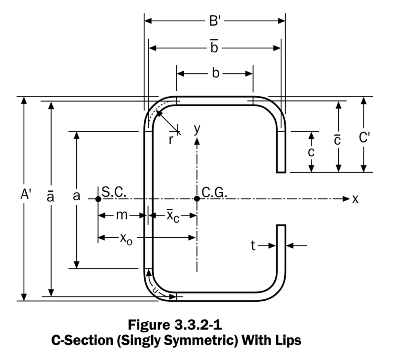
For back to back lipped channels connected at the middle of the webs AISI gives the following formula:-
![I_w=C_w=2\Bigg[\frac{\overline{a}^2\overline{b}^2t}{12}\Bigg[\frac{2\overline{a}^3\overline{b}+3\overline{a}^2\overline{b}^2+\Big[48\overline{c}^4+112\overline{bc}^3+8\overline{ac}^3+48\overline{abc}^2+12\overline{a}^2\overline{c}^2+12\overline{a}^2\overline{bc}+6\overline{a}^3\overline{c}\Big]}{6\overline{a}^2\overline{b}+(\overline{a}+2\overline{c})^3-24\overline{ac}^2}\Bigg]\Bigg]](https://engineervsheep.com/wp-content/ql-cache/quicklatex.com-a9d8eec9f0cd2cbe49464c6cfddb3138_l3.png "Rendered by QuickLaTeX.com")
Evaluating this gives 
So going back to basics and testing a single channel I came to the conclusion the published properties must have used some estimation formula for the torsion & warping constants that ignore the radii like the example equations above, and are therefore based on a square cornered channel.
Creating a square cornered channel and a round cornered channel in section-properties and doubling the  , and seemed to confirm that at least the AISI formula is a pretty good fit. But it also highlighted the disparity in the published properties with respect to the warping constant (and confirmed the fact that the published values are in fact based on twice the square cornered channels values for and at least).


2A = 578.00 vs (592.00) Error = -2.422%
2I_w = 559360923.53 vs (493100000.00) Error = 11.846%
2J = 258.50 vs (266.00) Error = -2.903%
2A = 592.44 vs (592.00) Error = 0.073%
2I_w = 594309512.79 vs (493100000.00) Error = 17.030%
2J = 266.24 vs (266.00) Error = 0.089%
You’ll note at this point that the square channel values agrees very well with the published and values. For the warping function the analysis value of  agrees pretty well with the AISI formula result of
  . Looks like the published properties have taken a shortcut and used some other simplified approach because the published value of
  seems a fair way off both the FEM, and AISI values. At this point I basically have no idea how they arrived at this number, so…
Which value to use?
So with so much choice and variations on finding one true value, which value should you choose?
If it were me, I’d go direct to the FEM result, as a bonus you also get all the other properties calculated from first principles in one sweep, and who is going to want to go through all those nasty hand calculations anyway. After all this is the theoretical value.
The AISI formulas do a reasonable job for the warping constant if you can live with the approximation of rounded corners vs square corners, but who knows how this scales. Presumably the error involved becomes more significant as the radii increases.
Conclusion
In this post we’ve demonstrated the fact that even manufacturers of these products aren’t immune to taking the easy way out and using simplified formulas that are at best an estimate of the true properties, and at worst could be significantly different! So it pays to check, many manufacturers publish information on how section properties have been derived, many don’t.
We also highlighted the need to verify that random formulas we might find on the internet are correct and fit for purpose. Don’t be that person who only plugs and chugs random formulas!
Lastly we used Python to get an accurate estimate of the true warping constant using the section-properties package and made the world of cold formed section design a better place, proving all approximations can indeed be rather approximate depending on the circumstances.
Very nice post and cheers for the plug 😉 Enjoying the content here – looking forward to seeing how your concrete program comes along!