In this part we cover adding a tee to the flange of an I-Section. It’s a good way of increasing the bending resistance of a beam or stiffening it up if you’re improving the deflection performance as there’s a good benefit to be had from increasing the overall depth of the section. You of course have to have the room or clearances to be able to do this.
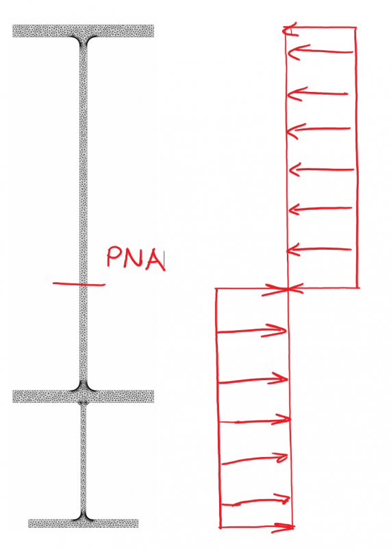
Firstly, let’s mention something else to be aware of when strengthening members, this is accounting for the existing load we have in the member at the time of adding the strengthening. Typically for bending we are trying to mobilise the full plastic section capacity of the section for a compact section. So, it comes as no surprise that if you review the force distribution at the point of full plastification of the cross section that this is independent of any locked in forces that might have been present before we added the nice unstressed strengthening elements to the original member. The capacity is the same irrespective. Sure the progressive plastification of the cross section is a bit more funky with certain parts yielding before others. But the end result for pure flexure is always this distribution of stress similar to below no matter how you started out: –

For deflection it’s another matter altogether. Plain and simple, you need to account for the deflection locked in at the time of the strengthening. Then the stiffer strengthened member is only stiffer for the portion of the load added over and the load/stresses that were locked in.
So, whacking the final strengthened members stiffness into your analysis program and then applying the entire load to it will underestimate the total deflection your system might see in real life. Unless of course you are somehow taking deflection out of the system prior to adding the strengthening. Maybe you’re jacking some of the deflection (and hence load) out of the system, so more of the final load is carried by the composite strengthened member and there is potentially less locked in load.
Don’t forget about this as it can be significant, often you’re strengthening for deflections when all of the dead load and some portion of the live load might already be on the member. The additional load added to get to your serviceability limit state (SLS) load case (especially if the loads are not increasing) might only be some small portion of load over and above what has been locked in, so you might not see the benefit expected if you are assuming your analysis with final member stiffness is correct.
Basically, ignore locked in forces for strength, but for deflections think about what you are doing and don’t be a sheep.
The code…
import copy
import sectionproperties.pre.sections as sections
from sectionproperties.analysis.cross_section import CrossSection

# -------------------------------------------------------------
# Inputs
# -------------------------------------------------------------

d = 612  # I section depth
b_f = 229  # I-section flange width
t_f = 19.6  # I-section flange thickness
t_w = 11.9  # I-section web thickness
r_1 = 14  # I-section root radii

d_tee = 202  # strengthening tee depth
b_tee = 178  # strengthening tee flange width
t_f_tee = 12.8  # strenghtening tee flange thickness
t_w_tee = 7.8  # strengthening tee web thickness
r_1_tee = 11.4  # strnegthening tee root radii

gap = 0.5  # gap between section and tee

weld_size = 6  # weld size

n_r = 50  # number of points considered around root radii

mesh_area = 10  # max mesh size

# -------------------------------------------------------------
# Calculations
# -------------------------------------------------------------
# create constituent geometry
# weld base geometry
weld = sections.CustomSection(
    points=[[0, 0], [weld_size, 0], [0, weld_size]], facets=[[0, 1], [1, 2], [2, 0]], holes=[], control_points=[[weld_size / 3, weld_size / 3]]
)

# I-Section beam
geometry1 = sections.ISection(d=d, b=b_f, t_f=t_f, t_w=t_w, r=r_1, n_r=n_r, shift=[-b_f / 2, -d / 2])

# strengthening tee
geometry2 = sections.TeeSection(d=d_tee, b=b_tee, t_f=t_f_tee, t_w=t_w_tee, r=r_1_tee, n_r=n_r)
geometry2.mirror_section(axis='x', mirror_point=[0, 0])
geometry2.shift = [-b_tee / 2, -d / 2 - gap]
geometry2.shift_section()

# weld 1 & 2
geometry3 = copy.deepcopy(weld)
geometry3.mirror_section(axis='x', mirror_point=[0, 0])
geometry3.shift = [t_w_tee / 2, -d / 2]
geometry3.shift_section()

geometry4 = copy.deepcopy(geometry3)
geometry4.mirror_section(axis='y', mirror_point=[0, 0])

# total number of individual geometry elements
geo_number = 4

# assemble geometry list
geo_list = [globals()[f'geometry{i}'] for i in range(1, geo_number + 1)]

# create merged section
geometry = sections.MergedSection(geo_list)

# add holes for gaps between I-Section and strengthening tee
if not gap == 0:
    geometry.add_hole([0, -d / 2 - gap / 2])

# clean geometry
geometry.clean_geometry(verbose=True)

# create mesh
mesh = geometry.create_mesh(mesh_sizes=[mesh_area] * geo_number)

# create section
section = CrossSection(geometry, mesh)

# calculate results
section.calculate_geometric_properties()
section.calculate_plastic_properties()
section.calculate_warping_properties()

# -------------------------------------------------------------
# Display results
# -------------------------------------------------------------
# plot results
section.plot_mesh()
section.plot_centroids()

# display all results
# check https://sectionproperties.readthedocs.io/en/latest/rst/post.html for definitions
section.display_results(fmt='.3f')For this configuration one thing I’d like to point out, since you essentially have a section made up of flat plates (ignoring the weld and root radii). If you add the torsion constants of the original beam and the strengthening tee (which include the roots anyway) you’ll get a good estimate of the torsion constant for the entire member.
After all you’re just creating a larger section that is still made up of flat plates, so the old ![]() should stand true still for an open section.
should stand true still for an open section.
Later, until part 5