As far as I can tell, Bluebeam has all but become the defacto standard for electronically marking up PDF’s in structural engineering consultancies.
By default, it basically comes with nothing to make your job easier as a structural engineer when it comes to structural specific mark-ups.
Sometimes I wonder what goes on at the developers table… “how about we create this awesome tool engineers can use, but it would be better if we didn’t help them out too much, actually let’s just concentrate on making the interface prettier….. They’ll appreciate that right?!“
Well I do appreciate a slick user interface, but on the other hand there are no built-in out-of-the-box mark-up tools (Toolsets in Bluebeam lingo) supplied specifically for structural engineers. Would it be too hard for example to have a tool or libraries that could replicate common structural steel shapes from around the world, or concrete beam cross sections generated based on entering some defined cross section parameters like width and height.
Make things a little more intelligent please, is that too hard to do? Well, I can only imply that apparently it is because no tools of this type exist as far as I’m aware in the pdf world. Nothing is probably coming on the horizon either.
Hopefully, the interface gets nicer looking though, I like that.
Seriously there must be some opportunity here to make an excellent product more awesome (and useful in the process) by adding more features like this out-of-the-box…..
The best thing we can do here is to create our own Toolset populated with standard sections and use the built in Toolset functionality to make our own installation of Bluebeam just that tiny bit more awesome. Not particularly intelligent like something that could actually be provided by the developers, but obviously better than the nothing, nada, zip provided by the out-of-the-box experience!
This post will go over the basics of how to do this, and finally force me to actually do it myself whilst maintaining some will to live through the exercise. Essentially repeating some boring process over and over sums up structural engineering some days/weeks/months, but I don’t have to like it.
Rinse and repeat 100 times…
First thing we need to do is print out to scale all the sections we want in our library from whatever CAD program we use. Take note of the scale you printed for later.
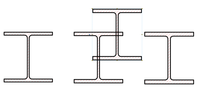
Then one by one zoom in and take a snapshot (keyboard shortcut G), stick as close to the line as possible without going onto/over the line. If you have a mouse that you can adjust the sensitivity on, cranking it down will help with getting this as accurate as possible. Paste the snapshot into the same pdf or a new pdf.
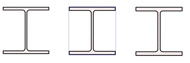
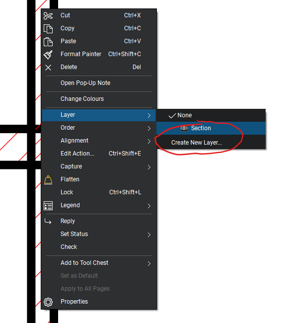
Right click the pasted snapshot and add it to an appropriately named layer, I used a layer called section. This is not mandatory, but it does give you the opportunity in the future to turn the visibility on and off for any sections you place as mark-ups, so it’s a damn good ideato do it.
Now select the section and rename the snapshot as per the sections size/designation. Also add the same size/designation as a comment.

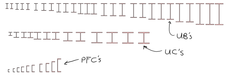
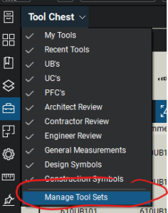
Create a new Toolset from the tool chest, name it something appropriate like the type of section you plan on storing in it. In my case I divided my sections into UB’s (Universal Beams), UC’s (Universal Columns) and so forth to keep thing organised.
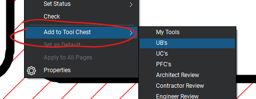
Now right click again on the snapshot and add it to the newly added Toolset.
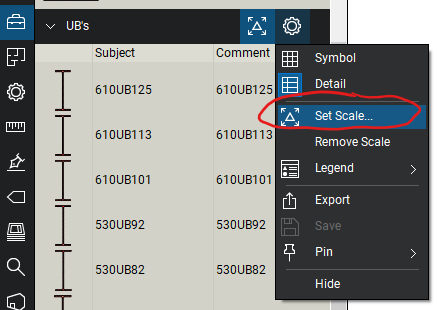
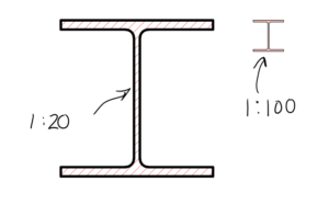
Lastly, set the Toolset scale to the original printed scale. This will mean they will be scaled correctly when placed as a mark-up when the scale on a page or viewport has been set/calibrated.
Rinse and repeat 100 times until finished (exact number may vary depending on how keen you are) … Good luck!
I’ve attached the toolsets I created for UB’s, UC’s and PFC’s below. These cover the standard section sizes available in New Zealand and Australia to save you the trouble of doing it yourself.
All up, it took an hour or so, and my will to live is intact….
Thanks guys, very useful!
Thank you Very useful… !!!!
Regards Kostas
Thank you! love your work!
Might be a very late reply on this but, a while back I needed to show some steel details (detailing steel is somewhat outside my wheel house) for a project I was working on. I also felt compelled – as you do – to look smarter than I am, so, I made an I beam using the ‘Polygon Sketch to Scale’ tool and filled it with a light lined diag hatch. I did it to scale and saved it to the toolchest. When I drop it onto any given page it scales to the page scale automatically. I found this to be preferable to snapshots so I can keep lines etc. consistent with other parts of my drawing.
This was something of a one off need and I just needed something representative, so I’m sure my dimensions are not accurate. So the shape can be altered, perhaps you might find it useful? It’s a pretty small contribution but I’d be happy to pass it on if you have an interest. Let me know where to send the BTX file.
Cheers! Matt R.
Thankyou for the download , Have you done created a SHS, RHS OR PIPE that you would also be willing to Share .
Thanks Andrew