It’s a question that seems to come up from time to time in my experience, can you take the point of inflection as a point of lateral restraint for the restraint of structural steel members under flexural forces?
The answer is of course… NO!
Let me say that again… NO, NO, NO!
Some people don’t ask obviously before doing, they just do it and are none the wiser.
But despite this, some sheep still try to argue the fact that there is something special about them that lets them try to do this even if the error of their ways is pointed out to them.
Many stating that their lecturer at University said so, or some random person on the internet said so, so it of course must be true. Not all lecturers were created equal obviously, despite all the letters after someones name this doesn’t always mean they know what they are doing.
Let me tell you that I’m just a random guy on the internet to. So this post sets out to prove this fact in a logical manner and settle the score once and for all. Engineer 1 v Sheep 0.
Here in this post we’ll demonstrate by using a rational buckling analysis that it’s simply not true, nor is it conservative, settling the argument once and for all.
The flawed thinking presented by some is that at this point the moment is zero, therefore there is no restraint force (typically in this part of the world it might be 2.5% of the critical flange force, but other standards differ a little). As such the argument is you don’t actually need a physical restraint because there is no force.
Some people just say it is a special magical property when the moment is zero that it’s somehow self restraining or something, I’d like to magic some ‘thinking’ into their brains to help with future life choices.
YES… this is basically this is a load of bollocks, and we’ll prove it later.
Background to the development of the 2.5% restraint provision
Real members have imperfections, no magic sorry. The 2.5% design force requirement while load based, is really a stiffness requirement in disguise. A practical restraint or lateral brace usually has sufficient stiffness by virtue of application of the strength requirement (this isn’t always the case, but it pays to think in terms of stiffness and strength when considering if a restraint is actually a restraint).
Lets delve a little deeper into this notion that stiffness is all that matters. This is most easily demonstrated in an axially loaded member because its conceptually the easiest thing to visualise:-
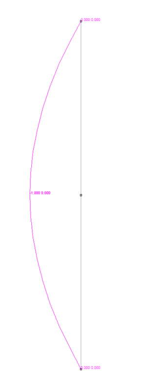
Take the following scenario, a pin ended column of length  with a horizontal spring at the center that partially restrains the section from buckling in the first mode. At zero spring stiffnesses our column buckles in the first mode with an effective length of
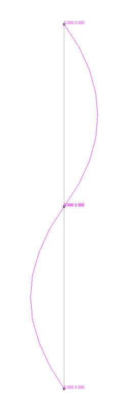
  . Ramping up the spring stiffness increases the critical buckling load. At some point if we make the spring stiff enough, it effectively forces a higher second mode of buckling with an effective length of
  . Fairly logical right!
Here’s an analysis prepared to demonstrate this principle by using a rational buckling analysis in Microstran to calculate the critical buckling load vs brace stiffness for a random column with mid-height restraint:-
Interestingly up until the point where the higher mode of buckling kicks in their is a linear relationship when comparing the spring stiffness to the load that is able to be carried by our partially restrained member (see graph below).
By altering the horizontal spring stiffness at mid-height of the above scenario we can determine the critical buckling load of the column at a number of data points through the use of a ‘rational buckling analysis’:-
| BRACE STIFFNESS | CRITICAL BUCKLING LOAD |
| 6000 | 553 |
| 5000 | 553 |
| 4500 | 553 |
| 4450 | 553 |
| 4425 | 553 |
| 4400 | 551.5 |
| 4350 | 547 |
| 4250 | 539.5 |
| 4000 | 517 |
| 3500 | 473.5 |
| 2500 | 383 |
| 2000 | 335.5 |
| 1500 | 287.5 |
| 1000 | 238.8 |
| 500 | 188.5 |
| 0 | 139 |
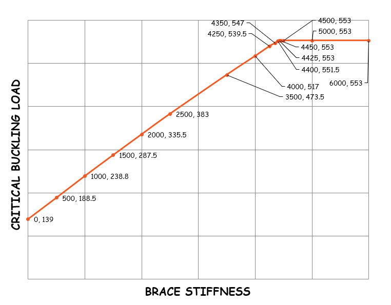
Hopefully to the observant among you, this demonstrates that the stiffness of the restraint is directly proportional to the load that is able to be carried. Additionally it shows that at some point if you make the restraint stiff enough it forces the second buckling mode (the horizontal bit of the line).
There were no loads in sight, because in practice the load carried by a restraint doesn’t really come into it. Someone simply came up with the 2.5% load as being a practical measure to achieve the required stiffness, and the rest is history as they say.
As an aside, Euler tells us that the critical buckling load in the second mode should be 4 times that of the first mode if the effective length is halved. In this example 553kN/4 = 138kN, verses 139kN, good enough in my book to prove my point that the arrangement satisfies Eulers column equation.
The theoretical stiffness at which the 2nd mode behaviour kicks in is:

For the geometry given this evaluates to approximately to a stiffness of 4447, compared with roughly 4425 from the Microstran analysis. Not bad I guess, I suspect it’s because Microstran is a bit of a rubbish analysis program to be honest.
Let me say it again, stiffness is what really matters for achieving effective restraint and driving higher modes of buckling (and hence increasing load carrying capacity). Stiffness is king.
I feel like this is something that is not well understood with modern codes application of only a load based approach to effective restraint.
Back to inflection points… Mastan2
Most codes have provisions for using a ‘rational buckling analysis’ to determine the theoretical critical buckling force at which something buckles. This can be either flexural or axial buckling dependant on the software.
It’s a useful little analysis method to have in your arsenal in times of need, when all things buckling are being debated. For example you no longer need to guess the effective length factor, its inherently taken care of in the analysis which gets rid of any guesswork.
I will point out that the critical buckling load from this type of analysis is not always the capacity, you’ll still need to apply your column or flexural member curves to account for second order effects (like residual stresses, out of plumbness, initial imperfections, etc).
Mastan2 is a handy free tool for the assessment of member stability. The interface can be a bit of a struggle, doing the most simple of things is a bit of a chore as it’s not what I would call intuative if you are used to more refined commercial analysis packages. By default many of the options you require won’t be enabled which doesn’t help if you’re just starting out.
So I highly recommend doing the Mastan2 Stability Fun tutorial modules to wrap your head around the program and to learn more about stability in general. But we are just going to jump right in and show some results, as this isn’t a tutorial in using Mastan2.
So I’ve setup the following model to demonstrate that with & without a central restraint that the buckling capacity is in fact different.
The basic model is shown below, the I-Section shapes are simply additional members so we can visualise what is going on with respect to member rotation:-

As we can see below we have a inflection point at midspan, with an equal moment being applied at each end of the member:-

Running an elastic critical load analysis with no intermediate restraint gives the following critical buckling load factor, being 7199399 (note this is simply the ratio by which you would need to increase the applied loads to cause elastic buckling).

Note also because we are doing a elastic critical load analysis, we aren’t specifically required to model any initial imperfections or allow for residual stresses as these are dealt with by application of the code requirements for these effects (work your way through the Stability Fun modules and you’ll know what I mean if I’m making no sense at all!).
The keen eyed among you will note at the point of inflection we have some twist of the cross section, and no lateral deflection of the cross section. As shown below:-
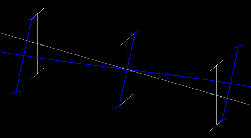
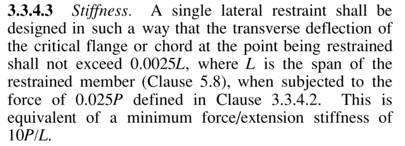
This aspect is important in the fight against use of the point of inflection as a point of restraint. So lets step back to what our codes generally say about providing restraint to a section in flexure.
Generally structural steel design codes are going to say something along the lines of you needing to prevent lateral deflection of the critical flange, and/or prevent twist of the section for a valid restraint. Each code might have a slightly different wording, but the intent is essentially the same.
So basically we need to either prevent twist of the cross section (nope, this isn’t going on at the point of inflection), or we need to prevent lateral deflection of the critical flange (nope, this isn’t occurring either at the point of inflection, as the top and bottom flanges are deflecting laterally due to the twist). So there we have our smoking gun, nothing about the point of inflection satisfies the general code requirements for provision of section restraint.
Now we add a restraint at the location of the point of inflection at mid-height, and run another elastic critical load analysis with the following results. As expected the load is exactly the same, because this pinned restraint at mid-height isn’t achieving any of the restraint conditions when located at mid-height. Again the critical buckling load factor is 7199399 (same as no restraint):-

Reality…
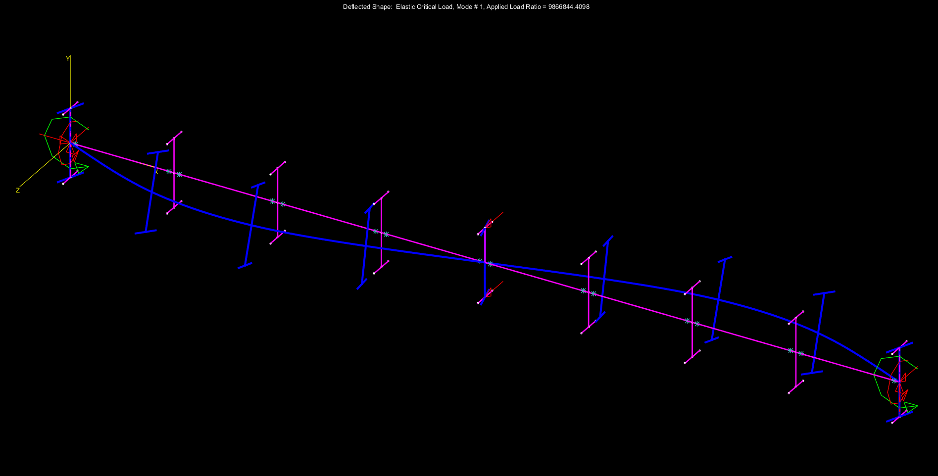
Move this restraint to the virtual top flange and bottom flange locations, and we’re starting to get into the realm of achieving some real restraint to the cross section (considering our code definitions for restraint, prevent twist/prevent lateral deflection of critical flange(s)), no magic involved.
Our updated restraints effectively prevent the lateral deflection of the critical flange, and prevent twist. You’ll see that the critical buckling load factor has now jumped up to 9866844, an increase of 1.37 times the previous value. This improvement is expected if providing a higher degree of restraint against lateral torsional buckling occurring.
Conclusion
So we have proved that taking a point of inflection as a point of ‘virtual’ restraint is a flawed approach. Don’t do it, stop doing it if you’ve done it. Don’t be that person ever again. Spread the word. $Profit!
Remember that stiffness of the restraint system is basically all that matters when restraining buckling. Stiffness is king. The load requirement in modern standards is simply a practical means of attempting to achieve the required stiffness. In older standards in this part of the world we even had a stiffness requirement that needed to be meet, but it was removed from more modern codes on the basis of practical restraints nearly always achieve the requirement, but is nearly always enough… think about that stiffness.
This is a really interesting article. I’m surprised they removed the stiffness clause (1981) from recent Standards!