Something that really irks me when checking others concrete designs, is the apparent lack of knowledge surrounding moment or tension reinforcement development. Along with the concept of moment coverage diagrams to prove that all regions of your member have sufficient moment strength. Isn’t this the point of designing the beam….. Arrgghhh!
Some people seem to design by checking the critical section at max moment and that’s basically it, they seem to think they can extend/terminate some reinforcement a fixed development length past the most critical point and they are golden.
Unfortunately, the Sheep of the world are usually wrong. Why are they wrong, well this approach may not cover the internal forces that are present due to tension lag effects (sometimes referred to as shear lag as well).
What is “tension lag effects” you might ask, well basically this is easiest to explain if you consider a beam and a strut and tie truss model that might represent the beam: –
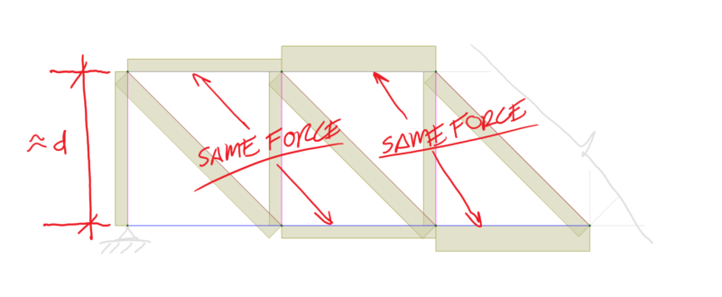
You will note in reviewing the top and bottom tie and strut forces that the horizontal tension/compression components of equal value are offset by an effective depth along the beam. From horizontal equilibrium they must be the same load.
So, what does this mean, well it means if you are extending your maximum moment reinforcing just Ld (a development length) from the point of max moment. Then the internal tension forces in the reinforcement one effective depth out from the critical section could be the same as the force at the opposite surface of the beam at the critical region. So, if you terminate the reinforcement too early you don’t cover this so-called lag effect. Bad news potentially….
The other thing to think about is if you are terminating some proportion of the reinforcement at the most critical region in terms of moment, then the reinforcement left over still must be capable of resisting the moment at the section after you’ve terminated this this reinforcement. Seems logical right, provide sufficient capacity to cover the moment demand. …. But like I said some people don’t pick up that there is more to structural design and checking than checking the region with the maximum moment from their analysis, even if the concrete standard tells you where the critical sections are (a big hint right?): –

So far simple right, so why do I seem to always come across people not checking these development rules for reinforcement? Have they never been taught, are the code provisions cryptic? Were they dropped on their head as a baby?
I really don’t know, but don’t be that guy/girl why doesn’t check this stuff.
So, what do we actually need to check, and how does one construct a moment coverage diagram? Easy, lets do it!
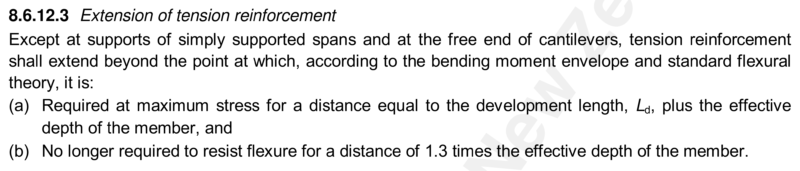
NZS3101 has the following provisions relating to the development of tension reinforcement: –
Other codes may have similar (simple) requirements.
So, taking a moment diagram (a beam experiencing some lateral loading with some applied gravity load), we plot the strength of the different levels of reinforcement we want to provide as a series of horizontal lines. We then draw some extensions of Ld+d and 1.3d from the relevant points where the maximum moment is, and where the lower level of reinforcement covers the moment demand. One of these dimensions will govern (the one that results in the longest extension from the point of max moment), resulting in the minimum acceptable extension of the bars being terminated from the point of maximum moment. Then knowing Ld for the bars being terminated we can come back along the span a development length and connect the dots.
Graphically this is illustrated below in the following images for cases where both the first and second criteria govern with different reinforcement strengths to illustrate both cases, and how to construct the resulting moment coverage diagram: –
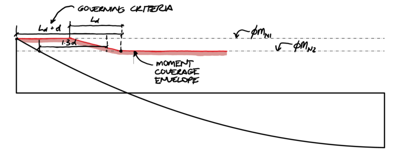

The moment coverage diagram is a measure of the moment capacity envelope provided along a member. It illustrates visually the buffer in moment strength you have at any particular location.
This buffer is provided by the correct application of the tension development rules. If you fail to apply these rules, you are inherently reducing the buffer available and you may inadvertently end up with a lower strength than the required capacity somewhere along your member.
This reduced capacity is best illustrated by an example where someone provides just a development length extension from the point of maximum moment. In this case the moment coverage dips below the moment diagram…. Pink = Bad news!

Why do we need a buffer you might ask? Well in addition to the tension lag effect noted earlier, in seismic design we also want to make sure if we have any plastic hinges forming at the critical regions that we don’t want for example another hinge forming further out in the span of a beam for example.
Ductile seismic design and the application of capacity design principles is all about forming dependable and predictable mechanisms after all (strong column/weak beam you may have heard of). If we can’t predict where our members might hinge and protect the other regions from the resulting overstrength loads, we might be in for a shock when Mr Earthquake pays a visit.
Theres a few other related things you might need/like to check, like ensuring you satisfy clauses related to development of bars at inflection points and ensuring you have sufficient shear coverage where you are terminating bars. Again virtually no one seems to check these additional provisions, and they do sometimes govern, but that’s for another day potentially ….. you’ve made it this far, so you know better…. Engineer 1 vs Sheep 0!