This post was inspired by a rather epic post at Eng-Tips forum, which came out of a seemingly simple request for some help on the segment length to consider for a continuous beam design to AS4100 (the Australian Steel code). Fast forward several hundred posts of debating issues of code interpretation, debates over critical flange definitions, everyone telling each other everyone else is wrong, backtracking, changing of minds, notionally proposing re-writing code clauses to suit particular sides of the argument, etc, etc. At the the end of it all there may or may not have been any real agreement reached, not unusual once engineers get to arguing.
You know when the original poster bows out at post #11, and the thread carries on for 200+ more posts that it’s a hot potato and there’s going to be a few virtual knife fights going down before it’s all said and done.
Basically any question on flexural torsional buckling or axial buckling on Eng-Tips seems to almost always create a good degree of rigorous debate. Bad good advice and even good bad advice can be had if you know where to look, good times they are a rolling….
Whether its about what effective length factor to consider for axial compression, or the effectiveness of certain restraint details for axial or flexural buckling. The advice is usually based on applying some dose of engineering judgement and/or some engineering guess-timation. Sometimes this might be conservative advice, other times not. The person who asked the question is sometimes left to their own devices to guess who is right or wrong once the dust has settled.
Sometimes the engineering shopper turns up to the party, shopping for an answer that makes their design work. Trying to convince themselves via some application of ‘group think’ mentality by seeking assurance or agreement for the exact answer they need to get their design to work. Often some of the answers are opposing their approach, but that doesn’t deter them for shopping for agreement, they only need one person to agree, right? Some random folks on the internet agree with their wonky logic, therefore they’ll take that as confirmation that they are on the right track…
The low down is that you basically don’t know if something that is deemed conservative is really truly actually conservative unless you do a more rigorous analysis to prove something was actually conservative. There’s probably some sort of fancy name for this aspect of design, but its the catch 22 of structural design or something. We strive to break things down to their simplest incarnation without losing sight of the fundamental behaviour and taking things too far.
Judgement & experience often comes into associating conservatism to design problems, and this takes some solid understanding of the relevant engineering principles underlying whatever the problems might be. So when a fresh graduate is trying to convince me the analysis or design shortcut they took was conservative, I’m never that convinced unless its so glaringly obvious like they doubled the load or something or have a damn good excuse or reason for doing so. This is opposed to taking the more rigorous approach and spending 5 hours working it out in a more correct way. But we don’t always have that luxury, time is money, and you can buy beer for money.
Elastic buckling analyses…
An elastic buckling analysis is a relatively simple analysis tool to have in your arsenal in any debate over buckling lengths, restraints, etc. In the correct hands it will allow you to analytically evaluate the stability of a beam or column under any given loading scenario. The perfect way to avoid becoming that person who has succumbed to the dark side of the guess-timation approach. Their column works if you guess a effective length factor of 0.85, vs the true effective length factor of > 1.0 if you took a more rigorous approach, its no way to live your life!
Unfortunately though, doing an elastic buckling analysis seems to be something that people really don’t understand that well. Applying the normal design provisions is easy right, we’ve all been taught them at University. There is also a wealth of information out there showing you how to apply the provisions as the authors of the standards intended.
But when it comes to a buckling analysis it’s open season for completely fucking things up and turning things upside down and back the front if you don’t appreciate exactly what you’re doing…. it’s not helped by the provisions in AS4100/NZS3404 being quite damn cryptic and hard to follow (I’m looking at you CL 5.6.4 & CL 6.3.4!). [Note all references given in this post are to NZS3404, but for the most part AS4100 should be similar]
CL 6.3.4 is a particularly poorly phrased clause, it’s subject suggests it’s only of relevance for members of varying cross sections, the clause before it (CL 6.3.3) specifically states that clause is for members of constant cross sections. But its basically the only information in the standard on how to correctly approach an axial buckling analysis. So having it buried in a clause that implies it’s limited to something else (and that only) is somewhat misleading as it applies to any buckling analyses.

The lack of design examples of real world design scenarios using buckling analyses doesn’t inspire you with confidence that this analysis you’ve never done before has been done correctly (or not) if you were to give it a crack.
So in an attempt to do the complete opposite of fucking things up, i’ll attempt to cover and breakdown the basics of doing both a flexural buckling check and a compression buckling check in accordance with AS4100/NZS3404 with some commonly available software.
Many analysis programs these days have options for undertaking buckling analysis. Basically there are two types of buckling checks that we as practical designers are interested in, not all programs handle the second case, so you have to know how your program of choice is approaching the analysis for the best results:-
- Critical buckling load analysis – this is an axial compression buckling check
- Flexural torsional buckling check – this is for evaluating flexural buckling
Typically if your analysis program has line/beam type members then in the background its doing an eigenvalue analysis, you may remember them from University. I do remember them in passing all these years latter, they were useful at one point in time regarding some matrix/maths things but largely one of those things you probably forgot as soon as the exam was over!.
The way a buckling analysis is intended to work in AS4100 & NZS3404 is you get out of the analysis a critical buckling axial load or moment. Think of this as the theoretical buckling load or moment. It’s important to recognise that this theoretical capacity for a perfect column or beam does not recognise the real behaviour of columns or beams when subject to axial buckling in compression or flexural torsional buckling in bending. There is no need to introduce any imperfections into your model, the code reductions take care of these second order effects.
Now the number one issue I see out there in the wild is people incorrectly using this reference buckling value as their capacity, so please don’t do this.
You use this “reference value” or theoretical value to apply the usual reductions to account for 2nd order effects like initial imperfections, residual stresses. These factors means that in real world columns and beams have less capacity as the theory applies to ‘perfect’ members. You might remember working out the Euler buckling loads for columns, this is basically what this theoretical value is for a column buckling analysis case.
The buckling analysis process is no different in practice than following the normal design provisions where you might be working out this theoretical value via an equation, and then applying some reductions to get a design capacity. Instead of using an equation, one way to think of it is you’re solving numerically for the reference value, and then carrying on like you normally would to calculate a design capacity using a few different equations and hopefully arriving at the same answer.
It’s just perhaps you may not have appreciating what was going on when plugging and chugging numbers into the normal formulas.
Now why do a buckling analysis? Well it allows you to calculate buckling capacities for cases that the formulas do not cover, some examples for axial buckling might for example be the following cases:-
- Cases where the axial load varies along the length of a member, truss chords are a great example of this concept, in this case what is the buckled shape or effective length, how many truss nodes might the chord buckle over?
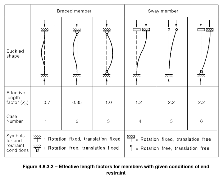
- Cases where the rotational or lateral restraint afforded by connecting members to the member ends doesn’t fit one of the idealised cases from figure 4.8.3.2, if your real member fixity is somewhere in between pinned and fixed, you might be left asking can I take advantage of this?
- Cases where the member geometry might change along the length of the member, such a splicing to a lighter weight section part way up a storey, what exact effective length would you choose here?
TLDR … A simple example to demonstrate the concept
To demonstrate this, lets do a quick example, because the above waffle is waffle until you can start to appreciate the simplistic beauty of the method.
We start with the design of an axially loaded member with one of the idealised fixity conditions noted above. This will hopefully demonstrate that using either method we are able to get essentially get the same capacity via two quite different analysis and calculation means.
Lets say we have an 8m tall 200UC60 grade 300 braced column with pinned ended connections (case 3 in the table above), and we want to know the axial load capacity via normal design procedures, and via a buckling analysis process? Well let’s do it side by side for comparison: –
Normal design process

Since we have contrived this perfectly pinned column scenario:-

Therefore the modified member slenderness for buckling about the minor (critical axis) in accordance with CL 6.3.3 is:-


Therefore we can now determine  using CL 6.3.3 noting that
  (note intermediate working not shown for brevity):-

Therefore the design member capacity for buckling about the minor axis direction is:-


Buckling analysis process
Since we have this contrived perfectly pinned column scenario with  we can take the Euler buckling load as follows from CL 4.8.2:-


Therefore we can now work out the modified member slenderness for buckling about the minor (critical axis) in accordance with CL 6.3.4:-


Therefore we can now determine using CL 6.3.3 noting that (note intermediate working not shown for brevity):-

Therefore the design member capacity for buckling about the minor axis direction is:-


First thing you’ll hopefully notice is that for all intents and purposes the same capacity has been calculated, because essentially the buckling effective length factor was assumed to be for both methods.
Now normally you wouldn’t calculate  like this, this value would come directly from the buckling analysis. Because we simply don’t know
  in a more complex scenario, which is the whole point of using the buckling analysis in the first place! Avoid being a guess-timator of effective length factors.
So, let’s prove this approach using a buckling analysis, imagining for a minute you don’t know what actually is for the pinned column. Also realise that your column could have any type of restraint or loading imaginable, the process is essentially the same:-
- Create a model of an 8m long column, add appropriate restraints top and bottom to represent the pinned behaviour
- Put a 1kN load on the column, the analysis will report the buckling multiplier (based on the applied loads) that loads would need to increase by to get a particular mode of buckling
- Some programs may require you to add intermediate nodes along the length of a member (generally 8 segments is desirable). Reading the manual is generally advisable
- Run a buckling analysis…
- Profit…?
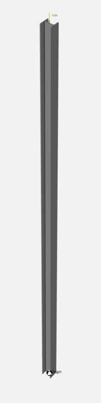
Our result below, reporting a factor/multiplier of  on our applied loading to initiate buckling.

This effectively means  . As we had
  of axial load in our column in the model.
This applied load of in the model is arbitrary, but it’s important to recognise that the elastic flexural buckling load is the product of the multiplier reported and the load in the member thats buckling in the model. If you were after the major axis capacity for our UC column, then you’d need to look for the next buckling mode, and so forth.
Conclusions are good
You’ll note the 644.9kN is the exact same answer as the example above using Eulers column buckling equation (collective sigh of relief). QED!
While we are working to AS4100 & NZS3404 here, most other standards around the world also allow the use of buckling analyses, for example AISC360 allows you to slot in the critical stress derived from a buckling analysis in place of evaluating some of their cryptic equations. So, the analysis method is very universal.
In the next post in this series we’ll use what we just learnt to do another example of a more complex real world example that would possibly be much harder to estimate the true effective length factor for compression buckling. But you’ll see, just plug and chug the same methodology as noted above, it’s as easy as that.
Hopefully later on we’ll get into an example or two of using a flexural buckling example by using Mastan2 and interpreting the CL 5.6.4 requirements. I’ve briefly covered the use of Mastan2 in this previous post if anyone made it this far!
Wow..this was an orgasmic reading.
I was so sure this was a spam comment until I saw your second comment on part 2. Glad you are getting this kind of enjoyment out of my ramblings!
Always glad to see engineers having a proper understanding of a buckling analysis.
I might have a play around with SpaceGass shortly with the same scenario outlined above.
Out of curiosity, I’m presuming you modelled a roller restraint at the top (point of application of load) of the column to allow the load path into the column?
Hi Mathew, yeah just restrained horizontally at the top in both directions. Restrained against translation in all 3 directions at the base along with a rotational restraint to prevent it spinning along its length.
That was very clear and enlightening. Comparing the two methods reinforces the topic of axial buckling in steel columns. Excellent work. Keep it up!