Part 4 – Integrals, its Business Time
In the first post in this series, I posted the following integral for the  direction centroid of a part of the compression block for EC2 parabolic-rectangular derivation.
At first glance the following integral looks a bit intimidating, but it breaks down to quite a simple formulation which I’ll try my best to explain in this post and the next post: –
![\overline{x}=\frac{\displaystyle{\int_{y_1}^{y_2}}\;\bigg[\frac{(x_1-x_2)(y_2-y)}{(y_2-y_1)}+x_2\bigg]\;\bigg[(1-(1-\displaystyle{\frac{y}{k_1c}})^n\bigg]\;\bigg[\frac{(x_{b\,mid}-x_{t\,mid})(y_2-y)}{(y_2-y_1)}+x_{t\,mid}\bigg]\;\bigg[dy\bigg]}{\displaystyle{\int_{y_1}^{y_2}}\;\bigg[\frac{(x_1-x_2)(y_2-y)}{(y_2-y_1)}+x_2\bigg]\;\bigg[(1-(1-\displaystyle{\frac{y}{k_1c}})^n\bigg]\;\bigg[dy\bigg]}](https://engineervsheep.com/wp-content/ql-cache/quicklatex.com-e8a3309f256423bc3763742836626c75_l3.png "Rendered by QuickLaTeX.com")
Firstly some basic ground rules that helped me and hopefully you as well to understand the whole process: –
It helps to conceptualise the whole process if you think of the physical shape of the concrete stress block as a three-dimensional volume, a volume of stress if you like. If you integrate or sum up all the stress in this volume you get the force acting on the compression region. For example the volume of the stress block is directly proportional to the force in this sense, find the volume and you’ve found the force. This volume of stress has a centroid, the resultant force representing the volume of stress acts through the centroid of this volume.
So, in short we need to work out the following two properties of the concrete stress block to make some progress: –
- volume of the stress block – which is essentially the force as outlined above (or proportional to the force if you assume the stress can increase from a factor of 0.0 to 1.0 times the specified 28-day concrete compressive strength without any other reduction factors applied of course)
- centroid of the volume of the stress block – which is essentially where the resultant force acts
Now, in terms of any arbitrary concrete cross section with part of the section in compression, if you define the neutral axis depth for convenience as an arbitrary datum with a value of  assigned for ease of explanation. With
  increasing in value working perpendicular to the neutral axis the extreme compression fiber (the point in compression furthest from the neutral axis).
If the general volume of a cuboid can be found by  , then it convenient to think about the problem in the following terms for developing our integral: –
 width of the concrete section at a given location, or the width of the compression block at a given
  the height of the stress block, in other words the stress at a given point (acting perpendicular to the axis of the member)
 the thickness of a thin sliver of the stress block working in the direction towards the top of the concrete section.
Then if we imagine slicing our stress block into an infinite number of these infinity thin slices with an area of  , with the infinitely thin sliver of the stress block such that the stress is essentially constant from one side to the other side (I’m sure this is coming back to you now), we could say its
  thick.
As the thickness approaches a limit of zero thickness (hopefully you can see where I’m going with this and are having flashbacks to high school calculus), the volume of one of these thin slivers is  .
.
So if you want the total volume of all of the infinitely thin volumes which is the total volume of the stress block, just sum up all the infinite number of infinitely thin volumes…… or another process for summing things mathematically like this is integration!
You remember finding the area under a curve right? well instead of areas we are simply dealing with volumes, which is almost the same.
So basically, we arrive at this general formulation: –
![volume = \displaystyle{\int_{y=0}^{y=c}\;\bigg[width \times height \times dy\bigg]}](https://engineervsheep.com/wp-content/ql-cache/quicklatex.com-1e6b75e8c8c87ced82b833921363ce83_l3.png "Rendered by QuickLaTeX.com")
where  is the distance from the neutral axis to the extreme compression fibre
So basically, if we have a formula for the height or stress at from our neutral axis depth written in terms of , and a formula for the width at from our neutral axis depth written in terms of then we are in business. If we substitute this formula into the general formulation, we are one step closer.
Our design code gives us the height term, which we just need to rearrange a little if we are not working with a constant stress like you would for a rectangular stress block. For example in EC2 the stress block formula for the parabolic bit of the stress block represented as a ratio of the stress  to design strength
  is: –
is: –
![height = \displaystyle{\frac{\sigma_c}{f_{cd}}=\bigg[(1-(1- \displaystyle{ \frac{\epsilon_{c}}{\epsilon_{c2}}}})^n\bigg]](https://engineervsheep.com/wp-content/ql-cache/quicklatex.com-a102301d53f750b03f38103cd0ed4b39_l3.png "Rendered by QuickLaTeX.com")
If written in this way the calculated ratio varies from 0.0 to 1.0, and because strains are proportional to distance from the neutral axis we can rewrite the above in terms of . Therefore by introducing actual distances of the transition point to the constant stress region and the distance from the neutral axis in place of the strains we can define the following: –
![height = \displaystyle{\frac{\sigma_c}{f_{cd}}=\bigg[(1-(1-\displaystyle{\frac{y}{k_1c}}})^n\bigg]](https://engineervsheep.com/wp-content/ql-cache/quicklatex.com-83f3992b04ba4a1986f07f3ae508ce6d_l3.png "Rendered by QuickLaTeX.com")
Note that the introduction of the  factor is simply defined as
So this height term is now written in terms of everything being known and which is the variable we are integrating with respect to. Half way there…
Generally, the width of the compression block varies as you work toward the extreme compression fibre, for example a square column bending about both axes narrows as you work your way from the neutral axis to the extreme compression fiber.
While we might have a section where the width varies as we move towards the extreme compression fibre, we will always be able to write a mathematical expression for the width of the section at a given dimension from the neutral axis in terms of that distance. Think of a circle for example, knowing we are some distance from the center, we can easily determine the width of the section written in terms of if we know the equation for the perimeter of the circle.
Similarly if the section we are looking at has sides that vary linearly we can define the width written in terms of between each location where the section changes shape. Any shape defined by a series of point coordinates is going to have the width of the edges varying linear as you move from the neutral axis to the extreme compression fiber, if those points are connected together with a straight line.
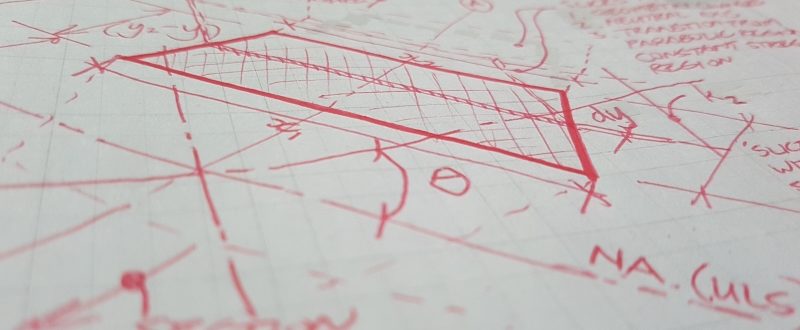
For a section with linearly varying sides, the width with respect to distance from the neutral axes is quite easily defined working from the fundamental geometry as our slice is essentially a parallelogram: –
![width = \bigg[\displaystyle{\frac{(x_1-x_2)(y_2-y)}{(y_2-y_1)}}+x_2\bigg]](https://engineervsheep.com/wp-content/ql-cache/quicklatex.com-a520b0deae2882c51f4751fc6c86c200_l3.png "Rendered by QuickLaTeX.com")
Where  is the width at the top of the slice at
  from the neutral axes, and
  is the width at the bottom of the slice at
  from the neutral axes. So, this width term is now written in terms of everything being known and which is the variable we are integrating with respect to. Three quarters of the way there…
Other similar relationships can be derived for other shapes with sides that do not vary linearly, for example the circle case, or an elliptical case, whatever takes your fancy.
Mathematically we would be evaluating our integral between some limits, being  and
and  , these being defined as distances from the neutral axis to where the shape of the section changes or other points of interest such as the transition point between the parabolic region and the constant stress region in the stress block.
If you like, its basically slicing the section horizontally parallel to the neutral axis at points where the geometry of the sides changes at our defined coordinates describing the geometry. Then you are doing an integral for each slice and simply summing all these individual integral results up to find the total force acting within the entire stress block.
So basically, at this point you have everything needed to develop a general integral that looks like the following for determining the force ratio for a section of the stress block with linearly varying sides using the EC2 parabolic-rectangular stress block (multiply this by the design concrete stress to get the final force obviously).
In the parabolic part the force is: –
![F_i=\displaystyle{\int_{y_1}^{y_2}}\;\bigg[\frac{(x_1-x_2)(y_2-y)}{(y_2-y_1)}+x_2\bigg]\;\left[(1-(1-\frac{y}{k_1c})^n\right]\;\bigg[dy\bigg]](https://engineervsheep.com/wp-content/ql-cache/quicklatex.com-f003b489dff4e394458fc15b8273f837_l3.png "Rendered by QuickLaTeX.com")
In the constant stress region  , so it simplifies to:-
![F_i=\displaystyle{\int_{y_1}^{y_2}}\;\bigg[\frac{(x_1-x_2)(y_2-y)}{(y_2-y_1)}+x_2\bigg]\;\bigg[1\bigg]\;\bigg[dy\bigg]](https://engineervsheep.com/wp-content/ql-cache/quicklatex.com-01a11def7e76d0348b5ebf71eb56c9b9_l3.png "Rendered by QuickLaTeX.com")
Conclusion
We are now able to calculate the force, noting similar relationships can be determined for any sort of shape.
I’ll cover determining the location of the centroid in the next post. Then once you know the force and location of this force, a force multiplied by this lever-arm is a moment. Then its ultimately business time because we are ultimately trying to find the moment capacity of a section under combined flexure and axial load!