Part 3 – Class Hell Week
At some point I came to the realisation that I’m going to need classes in my code, I didn’t know what they were exactly, but I needed them! Everyone else used them, so I must have them and they seemed the solution to a number of limitations I was coming up against or problems that needed solving according to good old google.
So I split up my code and copied it to the four corners of my project. Welcome to class hell, all my code that did work, now doesn’t work. Try as I might I just wasn’t getting it.
4 days later…..
Finally I start to get classes, though in my mind what I was doing on day one seemed to the same thing I was doing on day four, it just didn’t work on day one. Anyway things eventually got sorted and working again.
I then decide I need separate files, like pre-processing stuff in one file, the analysis stuff in another, and post-processing stuff in another. All being separated for ease of maintenance and dividing the code into logical chunks. Welcome to import hell, try as I might I just couldn’t get importing between the module files located in separate sub-directories to work.
4 more days later…..
Why the hell doesn’t Python let you import functions/classes from another file in another directory in the same parent folder without adding that parent directory to PYTHONPATH… if you know the answer I just don’t want to know, I’ve made my peace with it and moved on. Even an error message to this effect would have saved me from myself.
So adding the parent folder to PYTHONPATH solved all my issues immediately, but only after a lot of searching and trying every suggestion under the sun. This is because my package isn’t a package yet… doh.
2 days later…..
I discover that matplotlib can do xkcd style plots, consequently my faith in the universe has been restored. My little tool will now support this sketchy way of creating plots for extra lol’s (not by default though, you need to make a conscious decision to be awesome).
FYI, for laughs I throw down the challenge for structural engineers to include these xkcd themed outputs in formally published reports if they find some use for this tool when its completed. Do so and provide some evidence and I will add you to a wall of fame or something round here for posterity. Extra points and fame if its published in some respected/unrespected journal in this format.
Hopefully people finding it this useful is perhaps being overly presumptuous, I guess I’d be happy knowing other people find it useful…. Anyway onto something interesting:-
Reinforcing things
At some point during the above time frame I brought some reinforcement into the picture. Again relying on shapely for handling the geometry aspects, using the MultiPoint object. This is simply a series of points, or can even be a single point. I could have used a collection of Points or perhaps LineString objects (collection of Points connected by a line). But the MultiPoint object seemed the most logical. I had the idea that in the future if I defined the bars at the corners of sections, and if the object was a line I could easily divide the line and insert intermediate bars along the section edge through some future geometrical routine. I just ran into the small issue that if you have a single point, then it can’t be a line! Luckily converting between MultiPoint and LineString type objects seemed easy enough if this functionality is required in the future.
To define reinforcing we would eventually need both an x & y coordinate, a size for the bar and a yield strength or grade. So it’s basically turned out similar to defining the section geometry, the reinforcement inputs consist of some specifically formatted lists. One for coordinates, one for the size and lastly another for the grades.
The reinforcement coordinates describing each bar can be built up from multiple separate lists (termed reinforcement groups), or simply one long list describing the x and y coordinates of each bar. Perhaps best demonstrated with the example below:-
# Group 1, all 12mm and 300MPa:-
reinf_group_1 =  [(130, 130), (100, 230), (35, 140), (175, 175), (375, 40), (560, 35)]

# Group 2, mixed sizes and 500MPa:-
reinf_group_2 = [(475, 35), (540, 140), (390, 275), (405, 255), (490, 395), (500, 340), (510, 250), (485, 170), (35, 35)]

# assemble final reinforcement coordinate list by adding them together as comma separated lists:-
reinf_coords = reinf_group_1, reinf_group_2

# creates the following nested list (note you could enter it directly in this format as well):-
reinf_coords = [[(130, 130), (100, 230), (35, 140), (175, 175), (375, 40), (560, 35)],[(475, 35), (540, 140), (390, 275), (405, 255), (490, 395), (500, 340), (510, 250), (485, 170), (35, 35)]]

# internally within a processing routine this list is converted into the following flattened single level list which can then be utilised further by future code:-
reinf_coord_list = [(130, 130), (100, 230), (35, 140), (175, 175), (375, 40), (560, 35) , (475, 35), (540, 140), (390, 275), (405, 255), (490, 395), (500, 340), (510, 250), (485, 170), (35, 35)]
In addition to the coordinates, each bar requires a size and a yield strength/grade, so bar size and grade raw inputs can be built up in a similar manner following the following three rules:-
- Provide 1 bar size/grade for all bars in all reinforcement coordinate groups, or
- Provide 1 bar size/grade for all bars in a single reinforcement coordinate group, or
- Provide individual bar sizes/grades for each individual bar in a reinforcement group
Note you can mix and match, in the sense that the bars in a reinforcement group could all have different bar sizes (defined using option 3), but could all have the same grade (defined using option 2 with a single value).
This flexibility enables quite a few options for dividing up the reinforcement into manageable chunks or diving in and having the longest list in the world. I personally recommend putting it all in logical groups so things are easier to manage. The methodology for assembling the final raw inputs offers the ability to analyse multiple reinforcement configurations with minimal effort. For example if you have to analyse the same reinforcing layout save for a few bars that are a different size or variable size in the same section, then separate these out, loop through the analysis just changing these reinforcing groups and keep everything else the same.
This concept is again best demonstrated by an example following on form the reinforcement coordinate groups defined above:-
# for group 1 we identified above all bars were going to be 12mm and grade 300:-
bar_sizes_group_1 = [12]
bar_grades_group_1 = [300]

# similarly for reinf_group_2 if we wanted a random selection of bar sizes and grade 500, we could define the following with one entry for each bar in group 2:-
bar_sizes_group_2 = [16, 16, 10, 10, 20, 25, 12, 12, 20]
bar_grades_group_2 = [500]

# assemble final reinforcement bar size and grade lists by adding them together as comma separated lists:-
bar_sizes = bar_sizes_group_1, bar_sizes_group_2
bar_grades = bar_grades_group_1, bar_grades_group_2

# This creates the following lists (note you could enter it directly in this format as well):-
bar_sizes = [[12], [16, 16, 10, 10, 20, 25, 12, 12, 20]]
bar_grades = [[300], [500]]

# internally within a processing routine this list is converted into the following flattened single level list which can then be utilised by future code:-
bar_sizes_list = [12, 12, 12, 12, 12, 12, 16, 16, 10, 10, 20, 25, 12, 12, 20]
bar_grade_list = [300, 300, 300, 300, 300, 300, 500, 500, 500, 500, 500, 500, 500, 500, 500]
Therefore hopefully you can see that the lists used internally within the tool are simply a list assembled from the users input with the coordinate, bar size and grade all at the same indexed location in the list.
The coordinates list as noted above are turned into a shapely MultiPoint object, so it can be translated, rotated and other such things so its kept with the defined concrete section geometry. For the reinforcement defined above this simply looks like this:-
>>>base_section = MultiPoint(reinf_coord_list)

>>>print(base_section)
MULTIPOINT (130 130, 100 230, 35 140, 175 175, 375 40, 560 35, 475 35, 540 140, 390 275, 405 255, 490 395, 500 340, 510 250, 485 170, 35 35)
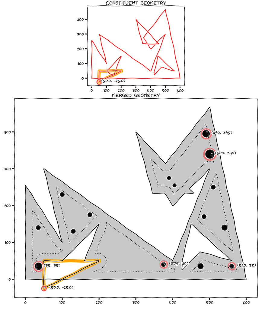
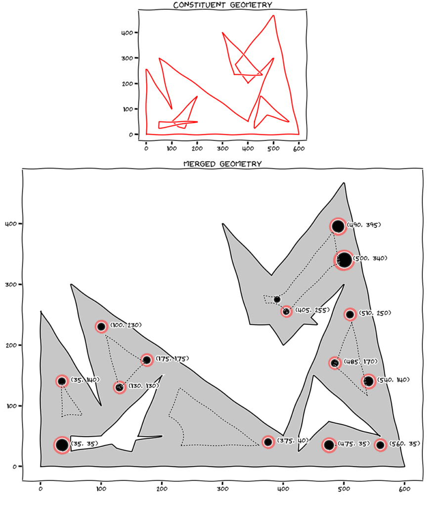
For kicks I went on a bit of a side mission at this point and added in some code to have the option to check a specified minimum bar cover, and things like identifying invalid bar placement (outside of the section or located within holes) and highlighting the offending bar to enable the user to review & correct the issue. I also threw in some checks on invalid section geometry (you know holes outside of the actual section and other such impossibilities in this particular universe) along with highlighting the offending constituent geometry that was defined incorrectly. This is basically so you aren’t left trying to determine which of the 1000 points defining your section is the one that needs to be changed.
This basically works on the principle of determining the least distance between the reinforcement and all the objects making up section (exterior, interior holes), and some offsetting of the perimeter of these objects to give a nominal cover line. You can see this in action below with some simple examples:-


Conclusion
Things seem to be progressing in the right direction, but so far I’ve ignored that damn integration mentioned in the first post and its role in determining the concrete force and location of that force. I’ll get all serious for a minute and address that in the next post and you’ll see why I chose such a god awful shape to test things out on, all those triangles, rectangles, trapezoids be kind to me on this one!
PS – I’m beginning to get sick of this object, I think it hates me some days… for example:-

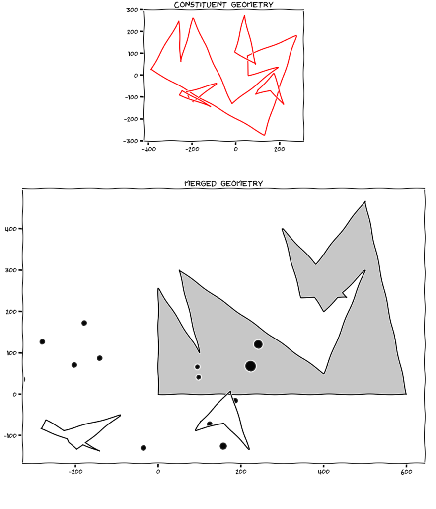
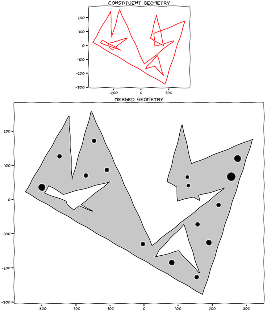
After some OCD debugging, it seems all those keyword arguments required when translating and rotating are actually doing something and I shouldn’t absentmindedly leave them out in part of the code or there will be consequences. Problem solved after some initial head scratching, at least it highlights the importance of plotting the geometry and raising appropriate exceptions to make sure what you think is going on is actually going on before you launch into any further analysis:-

