In this post we’ll try demystify CL 5.6.4 part b, what the hell does it really mean?
Well this is my take on it anyway… I can’t say for certain I’m correct as I’ve never seen anyone else use it, never seen an example, never used it in anger, etc. But the answers make sense.
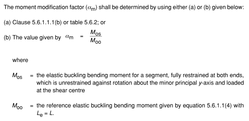
CL 5.6.4 cryptically states the following:-
So a couple of things here:-
- Regarding
 , basically it’s saying isolate the segment for which you are trying to calculate
  for, provide ‘F’ restraints at each end of the new member irrespective of what they are in reality, allow for minor axis rotation at the ends. Do a buckling analysis on this one segment.
 - Regarding
 , basically work out the reference buckling moment using the actual member length, substituting in equation 5.6.1.1(4)
  in place of
  .
. - Divide by …. boom
Easy right…
Now I will warn you that it’s a lot of work for almost no gain in my experience. In so far as you’ll calculate a very similar value for a whole lot of extra work, which may or may not matter depending on your actual moment demand.
So let’s work out using this approach using the same scenario we used in the previous post in this series.
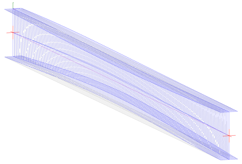
Previously we had this beam with ‘F’ restraints centrally and at ends, and for the left hand critical segment  :-
:-
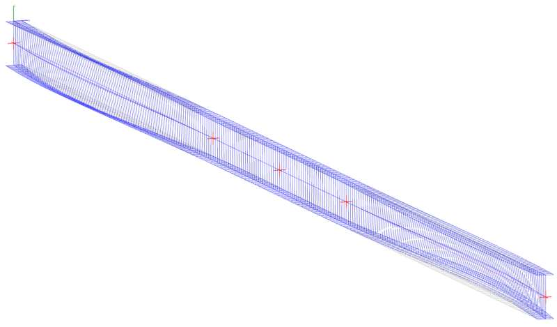
So basically we delete everything but the span of interest, and add some equivalent end moments to produce the same moment diagram.
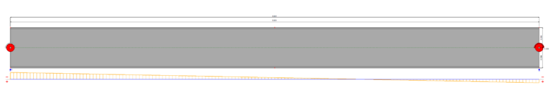

So basically 
Then all that’s left to do is to work out as follows using  in place of in equation 5.6.1.1(4). So for our 610UB125:-
![M_{oo}=M_o= \displaystyle{ \sqrt{\bigg\{\bigg(\frac{\pi^2\times205000\times 39.3\times10^6 }{8001^2}\bigg)\bigg[78846.15\times1560\times10^3 +\bigg(\frac{\pi^2\times205000\times 3450\times10^9 }{8001^2}\bigg) \bigg] \bigg\} }}](https://engineervsheep.com/wp-content/ql-cache/quicklatex.com-6b429b1cf2cdb71d7dcd05f6b696106b_l3.png "Rendered by QuickLaTeX.com")

Therefore:-


As you’ll note, a minor improvement over the previous value of which was 
That’s all there is to it really, was it worth the extra effort, you can be the judge of that. I personally wouldn’t bother in practice. But at least now you know how to interpret CL 5.6.4 part b to amaze your friends.
Excellent post – thankyou! This nicely ties in with part 3 of your series of posts on the topic.
Perhaps an idea for a future blog post is taking buckling to a truss with compression chord restraints in various arrangements? To make it more interesting the top/btm chords are continuous and it’s loaded with uniformly distributed loads (ie combined actions case).
Hi Trenno
Happy to consider if you could provide a bit more info on what type of restraint arrangements you were meaning. I was thinking you could demonstrate by using the code alignment curves vs a buckling analysis and see how close the two answers were (as never covered the use of alignment curves/charts previously). Generally, the question always seems to come up around how long should I consider the effective length for buckling of a chord for example, especially when there is a load reversal, is this kind of what you meant, or something else?
Sure, I was just mucking around with a test case:
8 bay, propped cantilever truss (2 bays cantilevering).
3m x 3m bays.
Transverse joint restraints at the top and bottom chords on the even bays (ie start/end and every 2nd bay).
This means that the bottom chord over the internal support has both tension/compression between lateral restraints.
UC254x89 sections. Verticals and diagonals pinned minor/major. Top/btm chords continuous.
20 kN/m SDL and 40 kN/m LL applied to top chord.
ULS Load combo: 1.35G + 1.5Q.
Max compression = ~978 kN
BLF = 3.14 with the top chord at Bay 1 displacing.
Hi mate, I was wondering if you could help me out with this question. When I’m using the AISC design capacity tables to check a beam, I always look at the section capacity and member capacity. Am I correct to say that, if I use stiffener plates spaced regularly in a PFC or UB for example, I can use the member capacity table for the length which the stiffeners are spaced?
Thanks
Hi Gabriel
Providing just a stiffener does not necessarily meet the requirements for a valid restraint for restraining the critical flange. You either need to prevent the lateral deflection of the critical flange, and/or prevent the twist of the cross section. If you refer to the code definitions for F/P/L restraints, you’ll find adding a stiffener along the length of a beam wouldn’t be enough as it does not prevent the lateral movement or twist of the critical flange.
The effective length for flexure is determined on the basis of the distance between valid restraints. The AS4100/NZS3404 codes have some quite good diagrammatic representations of various F/P/L type restraints that you can use to judge whether or not your given arrangement might qualify. Refer to section 5.4 in AS4100 and NZS3404.
Hope that clears things up?
That makes sense. Thanks for clarifying it.
Another case I often see is a steel beam with timber joists connected to it.
Many engineers would consider this beam with full lateral restraint and even use the Section Moment capacity in lieu of member moment capacity.
I was wondering if you do the same?
I think that would depend on how the joists are connected to the beam? Usually we have a timber plate bolted to the steel beam and the joists are nailed to the timber plate.
If the joists is over the beam..that would be another scenario to consider as well.
Figured it out 🙂